


D 13373.08
NOVEMBER 2007
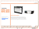
MPS
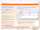
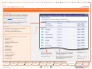
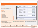
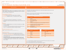
Table of
Contents
TANDBERG MPS
ADMINISTRATOR GUIDE
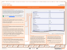
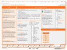
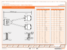
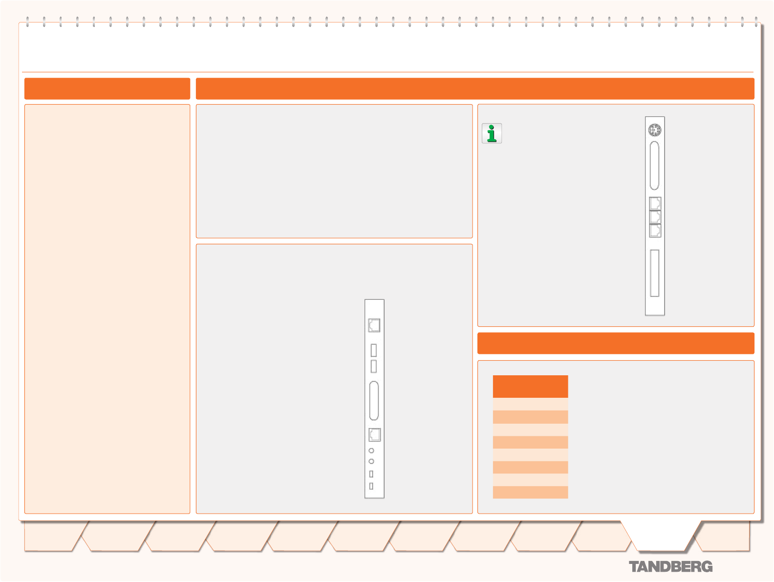
Rear View
Only the LAN interface Enet2
is in use. No other sockets
on the rear System Control-
ler Board are in use.
LAN Interface
The second LAN interface (Enet2)
of the System Controller Board is
accessible from the rear side.
The Enet2 interface is only in use if
you are connecting the MPS to two
separate IP networks.
Note that system management is
disabled on Enet2. The Enet2 inter-
face is only for call control.
2 x LAN / Ethernet (RJ-45) •
10/100 Mbps (Enet1 not in use)
System Controller Board Interface
Network Interfaces
Chassis System Controller Board Interface
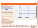
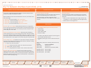
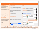
TANDBERG MPS 800
The TANDBERG MPS 800 has a 9U-19”
rack-mountable chassis that can host
up to 8 Media Processing Boards and 4
Network Interface Cards.
TANDBERG MPS 200
The TANDBERG MPS 200 has 3U-19” rack-
mountable chassis that can host up to 2
Media Processing Boards and 2 Network
Interface Cards.
Front Chassis
The TANDBERG MPS chassis is 19” rack-
mountable. On the front of the chassis is a
Liquid Crystal Display (LCD) for initial con-
figuration and basic system information.
You will also find 4 Light Emitting Diodes
(LEDs) for power status. The backplane
of the chassis is provided with advanced
CompactPCI technology for high speed
communication between the boards. You
will find 3 cooling fans in the lower front of
the chassis.
Rear Chassis MPS 800
The TANDBERG MPS 800 is shipped with
2 hot-swappable power units for configura-
tions of 1 to 3 Media Processing Boards. If
the unit has more than 3 Media Process-
ing Boards the TANDBERG MPS 800 is
equipped with 3 hot-swappable power
units. The power units are installed at the
back of the chassis. You will also find the
power switch/connector at the back of the
chassis.
Rear Chassis MPS 200
The TANDBERG MPS 200 is shipped with 1
power unit integrated in the chassis.
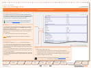
KB/MS
(Keyboard/Mouse)
(not in use)
Not in use
COM1
Enet1
(not in use)
Enet2
(Ethernet 10/100)
Serial 3/4
(not in use)
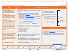
Rear View
LAN Interface
The LAN interface on the System
Controller Board is for manage-
ment/call control signalling.
1 x LAN / Ethernet (RJ-45) •
10/100 Mbps
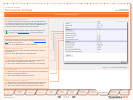
USB Interface
USB0 and USB1 are for future use.
Serial Port Interface
To use the asynchronous serial
port (J23) COM1 port, you need a
RJ-45 to RS-232 converter. This
port is configured as DCE.
ABT and RST Buttons
RST - Press and hold RST button
for a few seconds to restart the
system. Restart can also be done
via the LCD on the chassis.
CPU and FAIL LEDs
CPU LED - On when CPU activity
FAIL LED - On when parameter
inconsistency in boot code
10/100 BASE T
(Ethernet 10/100)
USB1
(not in use)
USB0
(not in use)
Not in use
COM1
(serial port)
ABT (not in use)
RST (Reset button)
CPU LED
FAIL LED
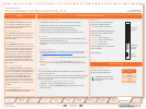
System Controller Board
The System Controller Board takes care of the following functions:
Call control•
System management•
The embedded Web server•
The LAN and Enet2 interfaces will allow you to connect to two different non-
overlapping IP-networks so that participants with no IP-routing between them
can be joined in the same conference. At least one Media Processing Board
must be connected to each network.
The 2 x LAN interfaces will also give the TANDBERG MPS support for two
Gatekeepers, one on each network.
COM1 Pinout
Pin Description
1 DCD
2 RTS
3 GND
4 TXD
5 RXD
6 GND
7 CTS
8 DTR
Serial Port Pinout
146
Introduction
Quick
Setup
Using
the MPS
System
Status
System
Configuration
Installation
Gateway
Configuration
MCU
Configuration
Appendices
Main
Technical
Descriptions