2-1
ON
I
O
POWER MODULE
AFS-16
1
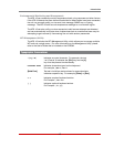
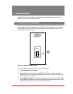
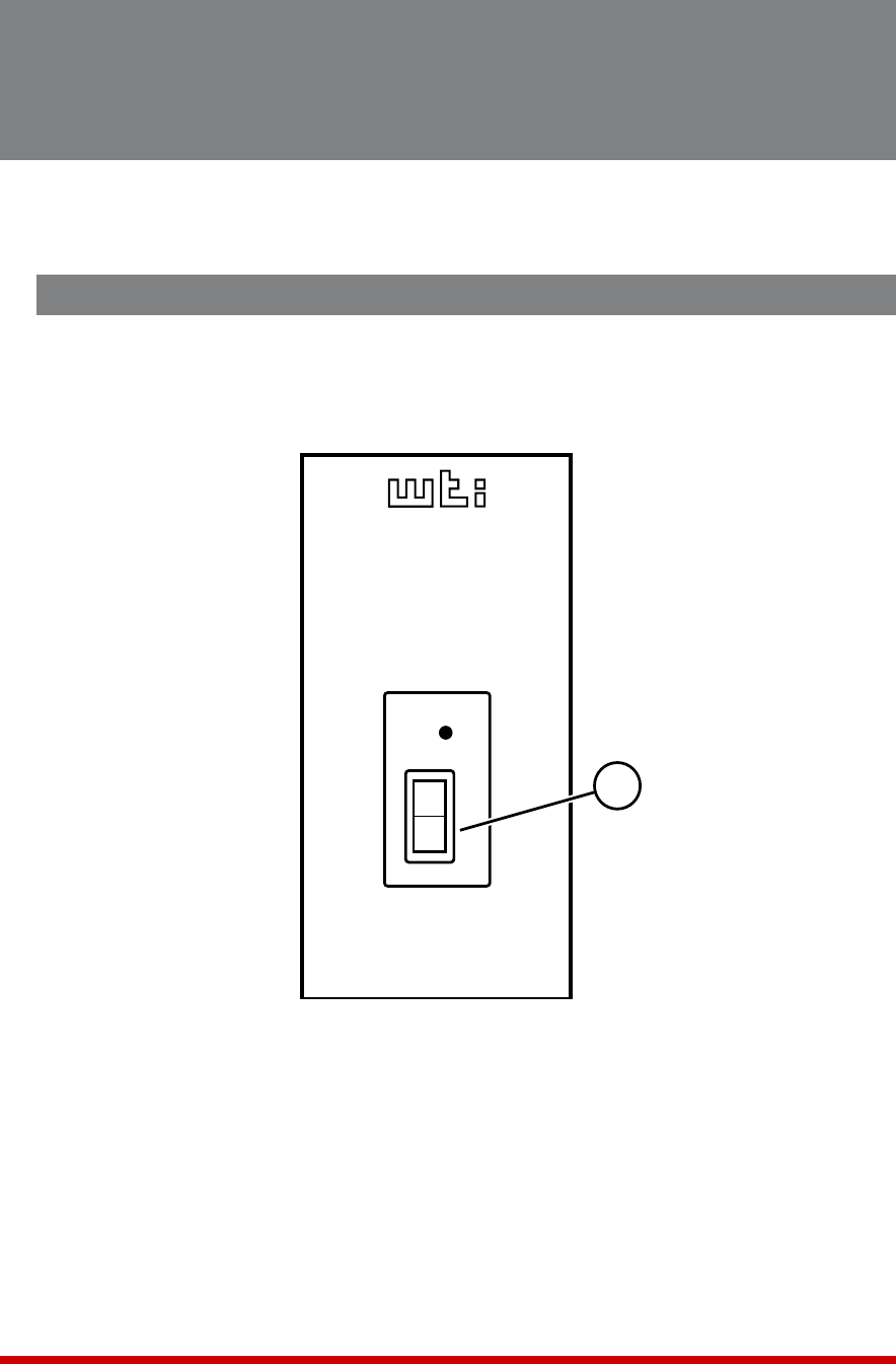
Figure 2.1: The Power Supply Module
2. Unit Description
The AFS-16 consists of a frame unit, one Dual Power Supply Module, one Control
Module, and up to sixteen Circuit Modules.
2.1. The Dual Power Supply Module
The Dual Power Supply Module, shown in Figure 2 1, provides AC power used by the
Control Module and Circuit Module(s). The AFS-16 will always include one Dual Power
Supply Module. Note that the Power Supply Module is not designed to be removed
from the AFS-16 Rack Assembly.
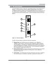
The Power Supply Module faceplate includes the following:
PowerSwitchandONIndicator
PowerInlets: (Not Shown) Two (2) IEC320-C14 AC inlets (located on the back
panel of the Dual Power Supply Module) which are used to connect the AFS-16 to
an appropriate power source.
PowerSupplyIndicators: Two LEDs (located on the back panel of the Dual Power
Supply Module), which will light when connected to an active power source. Note
that there is one LED for Inlet "A" and one LED for Inlet "B".


