4-2
Hardware Installation
4.3. Connecting a Local Control Device
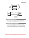
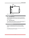
Use the supplied Ethernet cable and adapter to connect your PC COM port to the
RS232 Console Port on the AFS-16 Control Module as shown in Figure 4.1 and
Figure 4.2. For a description of the RS232 Port Interface, please refer to Appendix A.1.
4.4. Connecting an External Modem (Optional)
Access the AFS-16 Command Mode as described in Section 5.1 and then use the
Port Parameters menu to configure the RS232 Port for Modem Mode as described in
Section 5.8. Use an appropriate cable to connect your external modem the RS232 Port
on the AFS-16's Control Module and then connect your RJ11 phone line to the external
modem.
RJ-45
DB-9F
Pin No. Pin No. Signal
1
2
3
4
5 X
6
7
8
8
1
2
5
3
4
7
CTS
DCD
RXD
TXD
GND
DTR
RTS
Pin 8
Pin 1
Pin 1
Female
Figure4.1:DX9F-DTE-RJSnapAdapterInterface
AFS-16
RJ-45 DCE
Serial Port
Straight
RJ-45 Cable
DB-9M DTE
Console Port
DX9F-DTE-RJ
Snap Adapter
PC, Laptop
or Other
Device with
DB-9M DTE
Interface
Figure4.2:ConnectingDB-9MDTEDevicestotheAFSControlModule'sSerialPort


