2-3
Unit Description
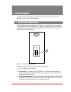
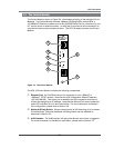
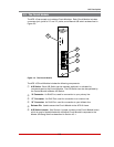
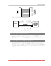
ResetSwitch: To reinitialize the AFS-16, hold the Reset Switch in the "down"
position for approximately five seconds. When the AFS-16 is reset, all users will be
disconnected from the AFS-16 and the operating system will be reloaded.
RS232Connector: An RJ-45 Serial Port for connection to your PC, control device,
or external modem. Please refer to Appendix A for a description of the RS232
interface.
AUXConnector: (Not Shown) A five terminal quick connector, located on the back
edge of the Control Module board. The AUX Connector can be used in conjunction
with the Monitor/Alarm Input feature to generate an alarm when the status of pin 4
changes. In addition, pins 1 through 3 on the AUX Connector can also be used to
switch a connected device On or Off in response to signal changes at Pin 4. For
more information, please refer to Section 7.
Notes:
• TheMonitorInputsignal(Pin4)isalwaysmeasuredrelativetothesignalat
thecommonground(Pin5).
• A"Low"signalshouldbebetweenZero(0)Voltsand-48Voltsanda"High"
signalshouldbebetween+5Voltsand+48Volts.
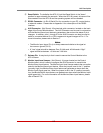
ReleasePin: A snap-lock pin that is used to secure the Control Module to the
AFS-16 frame.
MonitorInputLevelJumper: (Not Shown) A jumper located on the Control
Module board, which is used to configure the AUX Connector for use with the
Monitor/Alarm Input feature. The Monitor Input Level Jumper selects the non-active
state for the Monitor/Alarm Input feature. When the jumper is set in the "1" position
(normally high,) the Monitor/Alarm Input feature can generate an alarm when the
Monitor Input signal goes low. When the jumper is set in the "0" position (normally
low,) the Monitor/Alarm Input feature can generate an alarm when the Monitor Input
signal goes high. For more information on the Monitor/Alarm Input feature, please
refer to Section 7.6.


