AcerAltos 19000 User’s Guidexii
List of Figures
1-1 Pentium Pro Processor Architecture ........................................................1-2
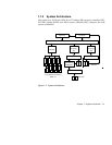
1-2 System Architecture...................................................................................1-3
1-3 Front Panel..................................................................................................1-7
1-4 Front Panel Features ..................................................................................1-8
1-5 RDM Button .............................................................................................1-12
1-6 Rear Panel.................................................................................................1-13
2-1 Front Lever and Support Pole...................................................................2-3
2-2 Connecting the Power Cable.....................................................................2-4
2-3 Connecting a Keyboard .............................................................................2-5
2-4 Connecting A Mouse .................................................................................2-6
2-5 Connecting a VGA Monitor ......................................................................2-7
2-6 Unlocking the Front Panel Security..........................................................2-8
2-7 System Power On.......................................................................................2-9
2-8 Microswitch Location ..............................................................................2-12
3-1 System Housing .........................................................................................3-1
3-2 Left Panel System Components ................................................................3-2
3-3 Right Panel System Components..............................................................3-3
3-4 Removing the Right Panel Door ...............................................................3-5
3-5 Removing the Upper Front Panel Cover..................................................3-6
3-6 Removing the Upper Front Panel Door ...................................................3-6
3-7 Removing the Lower Front Panel Door ...................................................3-7
3-8 Front Panel Board Connections ................................................................3-9
3-9 Attaching the Drive Guides ....................................................................3-11
3-
10 Installing an Additional Externally-Accessible Device.........................3-12
3-
11 Removing a Bracket Cover......................................................................3-13
3-
12 Installing a PCI Expansion Board ...........................................................3-14
4-1 System Board Layout.................................................................................4-2


