


AcerAltos 19000 User’s Guide
1-4
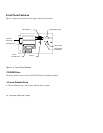
System Bus
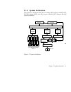
The system bus is the CPU’s major connection to all the system devices, primarily
the PCI and EISA bridges, and the memory controller. It can handle as many as
eight outstanding transactions at a time through a transaction pipelining feature,
in which consecutive tasks from the CPU are queued in and transported to the
designated devices on a first-in first-out basis. Pipelining allows for transaction
overlapping in different phases, as the CPU does not have to wait for each to
complete before it issues the next transaction. This produces significant
improvement in overall system performance.
The bus architecture supports a number of features that ensure high reliability. It
has an 8-bit error correction code (ECC) that protects the data lines and a 2-bit
parity code that protects the address lines.
The bus uses Gunning Transceiver Logic (GTL+) and a synchronous latched bus
protocol that simplifies timing constraints. This protocol supports higher
frequency system designs and along with GTL+, requires a low voltage which
reduces electromagnetic interference (EMI) resulting in a lower power
consumption.
PCI and EISA Buses
The system supports two PCI buses created by the two PCI bridge chips (PB).
The PCI buses serve as links between the PCI bridges and PCI devices onboard.
The presence of two buses instead of one reduces I/O bottlenecks and matches
the higher bandwidth of the CPU for faster data transfers.
The EISA bus connects EISA devices to other system devices through the
PCI/EISA bridge (PCEB) and the EISA system controller (ESC). The use of the
PCEB and ESC maintain compatibility within the EISA environment.