AcerAltos 19000 User’s GuideB-4
B.4 Hard Disk ID Feature
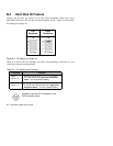
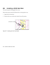
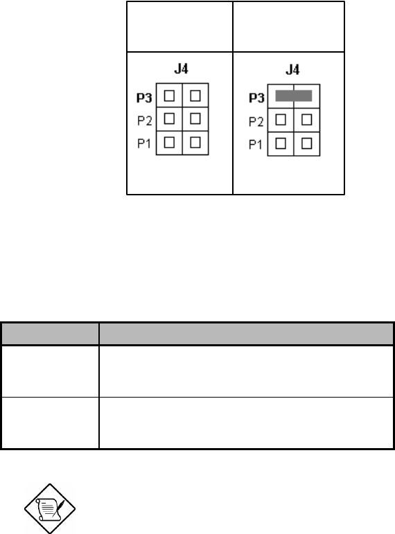
Closing the P3 pins on jumper J4 on the SCSI backplane board sets seven
additional SCSI drive IDs for the second backplane board. Figure B-4 illustrates
P3 settings for jumper J4.
Left
Backplane
Right
Backplane
P3 Open P3 Closed
Figure B-4 P3 Setting for Jumper J4
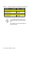
Table B-1 shows the P3 settings and their corresponding functions in two
‘combined’ channel configurations.
Table B-1 P3 Settings and Functions
P3 Setting Function
Open
(Bit 3 = 0)
Allows you to set IDs 0, 1, 2, 3, 4, 5, and 6 to
the SCSI drives on the left panel backplane
board. This is the default setting.
Closed
(Bit 3 = 1)
Allows you to set additional IDs 8, 9, A, B, C,
D, and E to the SCSI drives on the right panel
backplane board. This is the default setting.
Normally, hard disk ID7 is assigned to the
SCSI controller board.


