Chapter 4 - System Board 4-5
Voltage ID Settings
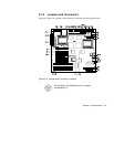
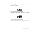
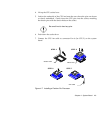
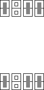
Figure 4-3 shows the settings of jumpers J2, J3, J4, and J5 to set CPU1 VRM
connector (J1) to 3.3V at 200 MHz.
J2 J3 J4 J5
Figure 4-3 VRM Settings for CPU1 (3.3V for 200 MHz)
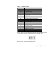
Figure 4-4 shows the settings of jumpers J7, J8, J9, and J10 to set CPU2 VRM
connector (J6) to 3.3V at 200 MHz.
J7 J8 J9
J
10
Figure 4-4 VRM Settings for CPU2 (3.3V for 200 MHz)
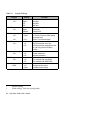
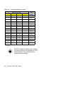
Table 4-2 lists the voltage identification (VID) code indicated by four binary-
weighted inputs.


