


2-54 Service Guide
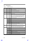
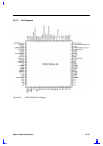
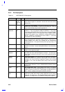
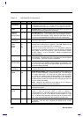
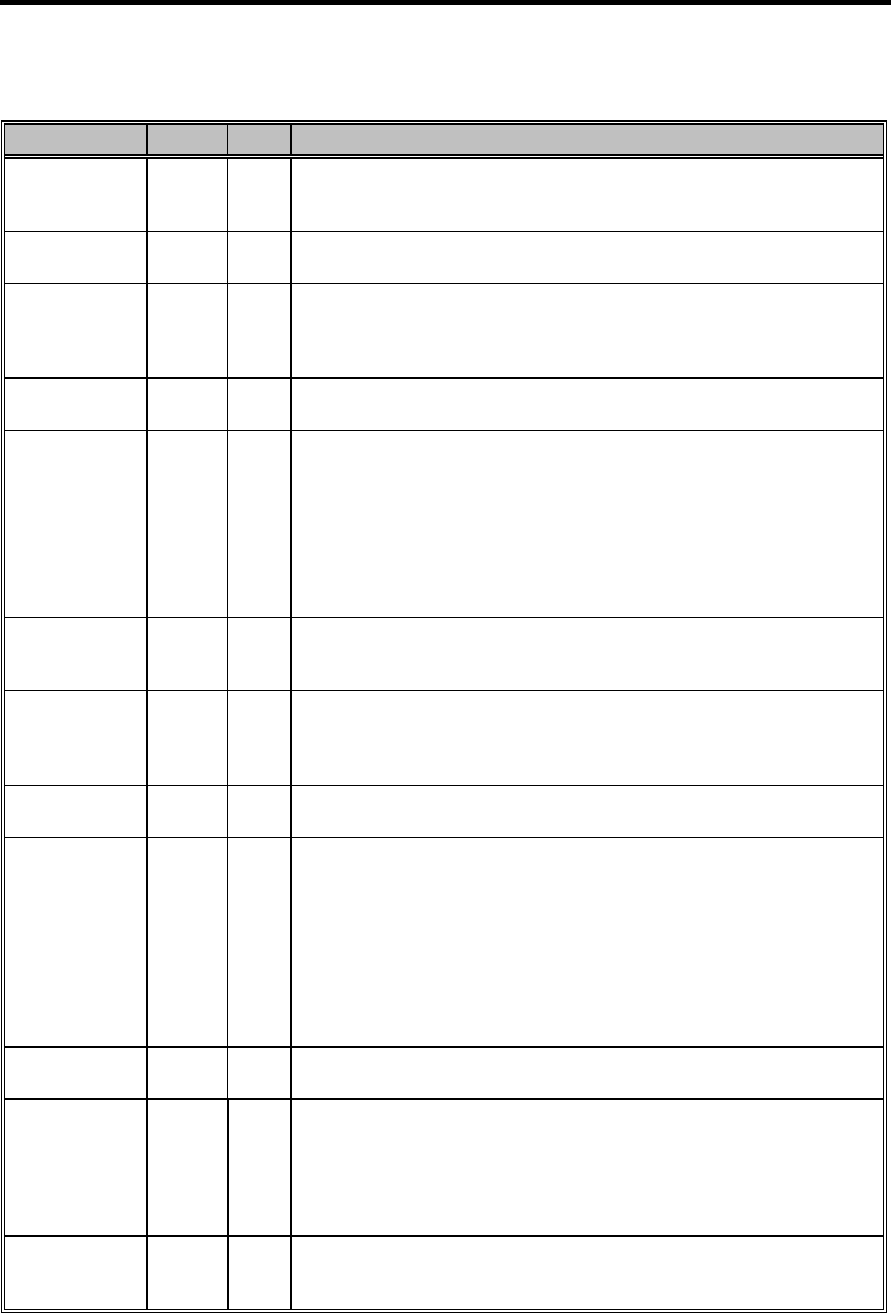
Table 2-6 NS87338VJG Pin Descriptions
Pin No. I/O Description
/DR1
(PPM Mode)
83 O
FDC Drive Select 1. This pin offers an additional Drive Select signal
in PPM Mode when PNF = 0. It is drive select 1 when bit 4 of FCR is
0. It is drive select 0 when bit 4 of FCR is 1. This signal is active low.
/DR23 47 O
FDC Drive 2 or 3. /DR23 is asserted when either Drive 2 or Drive 3 is
assessed(except during logical drive exchange).
/DRATE0
/DRATE1
(Normal Mode)
50, 49 O
FDC Data Rate 0, 1. These outputs reflect the currently selected FDC
data rate (bits 0 and 1 in the Configuration Control Register (CCR) or
the Data Rate Select Register (DSR), whichever was written to last).
The pins are totem-pole buffered outputs (6 mA sink, 6 mA source).
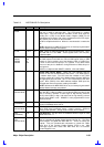
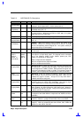
/DRATE0
(PPM Mode)
85 O
FDC Data Rate 0. This pin provides an additional Data Rate signal, in
PPM mode, When PNF=0.
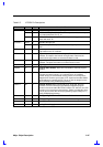
DRQ0
DRQ1
DRQ2
DRQ3
54
31
2
58
O
DMA Request 0, 1, 2. \An active high output that signals the DMA
controller that a data transfer is required. This DMA request can be
sourced by one of the following: FDC or Parallel Port.
When it is not sourced by and of them, it is in TRI-STATE. When the
sourced device is disabled or when the sourced device is configured
with no DMA, it is also in TRI-STATE. Upon reset, DRQ2 is used by
the FDC; DRQ0, 1, 3 are in TRI-STATE. DRQ3 is multiplexed with
IRQ15 and SIRQI1.
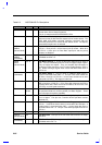
/DRV2 47 I
FDD Drive2. This input indicates whether a second disk drive has
been installed. The state of this pin is available from Status Register
A in PS/2 mode. (See PNF for further information).
/DSKCHG
(Normal Mode)
30 I
Disk Change. The input indicates if the drive door has been opened.
The state of this pin is available from the Digital Input Register. This
pin can also be configured as the RGATE data separator diagnostic
input via the Mode command.
/DSKCHG
(PPM Mode)
87 I
Disk Change. This pin offers an additional Disk Change signal in
PPM Mode when PNF = 0.
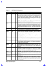
/DSR1
/DSR2
74,
66
I
UARTs Data Set Ready. When low, this indicates that the data set or
modem is ready to establish a communications link. The DSR signal
is a modem status input. The CPU tests the /DSR signal by reading
bit 5 (DSR) of the Modem Status Register (MSR) for the appropriate
channel. Bit 5 is the complement of the DSR signal. Bit 1 (DDSR) of
the MSR indicates whether the DSR input has changed state since the
previous reading of the MSR.
NOTE: Whenever the DDSR bit of the NSR is set, an interrupt is
generated if Modem Status interrupts are enabled.
/DSTRB 76 O
EPP Data Strobe. This signal is used in EPP mode as data strobe. It
is an active low signal.
/DTR1
/DTR2
69,
61
O
UARTs Data Terminal Ready. When low, this output indicates to the
modem or data set that the UART is ready to establish a
communications link. The DTR signal can be set to an active low by
programming bit 0 (DTR) of the Modem Control Register to a high
level. A Master Reset operation sets this signal to its inactive (high)
state. Loop mode operation holds this signal to its inactive state.
/ERR 77 I
Parallel Port Error. This input is set low by the printer when an error
is detected. This pin has a nominal 25 KOHM pull-up resistor
attached to it.