


2-70 Service Guide
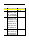
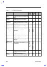
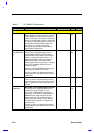
Table 2-7 CL-PD6832 Pin Descriptions
Pin Name Description Pin Number I/O Power
Power Control and General Interface Pins
SPKR_OUTt
Speaker Output: This output can be used as a
digital output to a speaker to allow a system to
support PCMCIA card fax/modem/voice and
audio sound output. This output is enabled by
setting the socket’s Misc Control 1 register bit 4
to ‘1’(for the socket whose speaker signal is to
be directed from BVD2/-SPKR/-LED to this
pin). This pin is used for configuration
information during hardware reset. Refer to
Misc Control 3 register bit 0.
128 I/O-
PU
4
LED_OUT/
HW_SUSPEND
#t
LED Output: This output can be used as an
LED driver to indicate disk activity when a
socket's BVD2/-SPKR/-LED pin has been
programmed for LED support. The Extension
Control 1 register bit 2 must be set to ‘1’ to
enable this output(to reflect any activity on
BVD2/-SPKR/-LED), and a socket’s ATA
Control register bit 1 must be set to ‘1’ to allow
the level of the BVD2/-SPKR/-LED pin to
reflect disk activity.
Serves as a HW_SUSPEND# input pin, when
Misc Control 3 register bit 4 is set to ‘1’.
This pin is used for configuration information
during hardware reset. Refer to Misc Control 3
register bit 1.
133 I/O-
PU
4
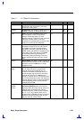
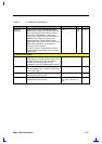
SCLK
Serial Clock: This input is used as a reference
clock (10-100 kHz, usually 32 kHz) to control
the serial interface of the socket power control
chips. CAUTION: This pin must be driven at
all times.
132 I
SDATA/
SMBDATAt
Serial Data / System Management Bus Data:
This pin serves as output pin SDATA when
used with the serial interface of Texas
Instruments' TPS2202AIDF socket power
control chip, and serves as a bidirectional pin
SMBDATA when used with Intel's System
Management Bus used by Maxim's socket
power control chip. This pin is open drain for
the SMB mode of operation and requires an
external pull up.
This pin is used for configuration information
during hardware reset. Refer to Misc Control 3
register bit 3.
131 I/O-
PU
2 or 3