


Major Chips Description 2-55
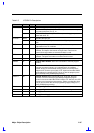
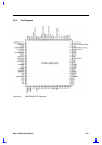
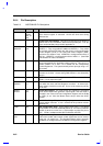
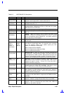
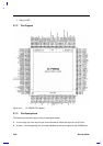
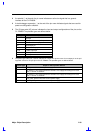
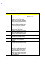
Table 2-6 NS87338VJG Pin Descriptions
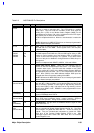
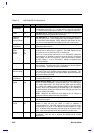
Pin No. I/O Description
/HDSEL
(Normal Mode)
32 O
FDC Head Select. This output determines which side of the FDD is
accessed. Active selects side 1, inactive selects side 0.
/HDSEL
(PPM Mode)
77 O
FDC Head Select. This pin offers an additional Head Select signal in
PPM Mode when PNF = 0.
IDLE 41 O
FDD IDLE. IDLE indicates that the FDC is in the IDLE state and can
be powered down. Whenever the FDC is in IDLE state, or in power-
down state, the pin is active high.
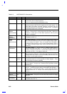
/INDEX 45 I
Index. This input signals the beginning of a FDD track.
/INDEX
(Normal Mode)
92 I
Index. This pin gives an additional Index signal in PPM mode when
PNF = 0.
/INIT
(PPM Mode)
78 I/O
Initialize. When this signal is low, it causes the printer to be
initialized. This pin is in a tristate condition 10 ns after a 1 is loaded
into the corresponding Control Register bit. The system should pull
this pin high using a 4.7 KΩ resistor.
IORCHDY 51 O
I/O Channel Ready. When IORCHDY is driven low, the EPP extends
the host cycle.
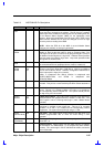
IRQ3, 4
IRQ5-7
IRQ9-11
IRQ12, 15
(PnP Mode)
99, 98
96-94,
55-57,
66, 58
I/O
Interrupt 3, 4, 5, 6, 7, 9, 10, 11, 12, and 15. This pin can be a totem-
pole output or an open-drain output. The interrupt can be sourced by
one of the following: UART1 and/or UART2, parallel port, FDC,
SIRQI1 pin, SIRQI2 pin or SIRQI3 pin.
IRQ5 is multiplexed with ADRATE0.
IRQ12 is multiplexed with /DSR2 and IRRX2.
IRQ15 is multiplexed with SIRQI1.
IRQ3, 4
(Legacy Mode)
99, 98 O
Interrupt 3 and 4. These are active high interrupts associated with
the serial ports. IRQ3 presents the signal if the serial channel has
been designated as COM2 or COM4. IRQ4 presents the signal if the
serial port is designated as COM1 or COM3. The interrupt is reset low
(inactive ) after the appropriate interrupt service routine is executed.
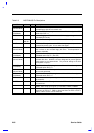
IRQ5
(Legacy Mode)
96 I/O
Interrupt 5. Active high output that indicates a parallel port interrupt.
When enabled, this pin follows the /ACK signal input. When it is not
enabled, this signal is tri-state. This pin is I/O only when ECP is
enabled, and IRQ5 is configured.
IRQ6
(Legacy Mode)
95 O
Interrupt 6. Active high output to signal the completion of the
execution phase for certain FDC commands. Also used to signal
when a data transfer is ready during a non-DMA operation.
IRQ7
(Legacy Mode)
94 I/O
Interrupt 7. Active high output that indicates a parallel port interrupt.
When enabled, this signal follows the /ACK signal input. When it is
not enabled, this signal is tri-state. This pin is I/O only when ECP is
enabled, and IRQ7 is configured.
IRRX1
IRRX2
65,
66
I
Infrared Receive 1 and 2. Infrared serial data input signals. IRRX1
is multiplexed with SIN2.IRRX2 is multiplexed with /DSR2 and IRQ12,
and IRSL0.
IRSL0,
IRSL1
66
6
O
Infrared Control 0, 1. These signals control the infrared Analog Front
End(AFE). IRSEL0 is multiplexed with DSR2, IRQ12, and IRRX2.
IRSL2 41 or
47
I
Infrared Control 2. These signals control the infrared Analog Front
End(AFE). IRSL2 is multiplexed with either /DRV2, PNF, /DR23 and
/SIRQI13, or with /MTR1 and IDLE.