


2-8 Service Guide
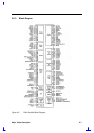
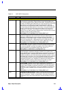
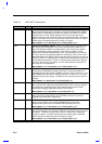
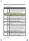
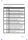
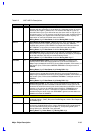
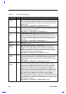
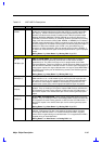
2.2.4 Pin Descriptions
This section provides a detailed description of each signal. The signals are arranged in functional
groups according to their associated interface.
The “#” symbol at the end of a signal name indicates that the active, or asserted state occurs when
the signal is at a low voltage level. When “#” is not present after the signal name, the signal is
asserted when at the high voltage level.
The terms assertion and negation are used exclusively. This is done to avoid confusion when
working with a mixture of “active low” and “active high” signal. The term assert, or assertion
indicates that a signal is active, independent of whether that level is represented by a high or low
voltage. The term negate, or negation indicates that a signal is inactive.
Certain signals have different functions, depending on the configuration programmed in the PCI
configuration space. The signal whose function is being described is in bold font. Some of the
signals are multiplexed with General Purpose Inputs and Outputs. The default configuration and
control bits for each are described in Table 1 and Table 2.
Each output signal description includes the value of the signal During Reset, After Reset, and
During POS.
During Reset refers to when the PCIRST# signal is asserted. After Reset is immediately after
negation of PCIRST# and the signal may change value anytime thereafter. The term High-Z
means tri-stated. The term Undefined means the signal could be high, low, tri-stated, or in some
in-between level. Some of the power management signals are reset with the RSMRST# input
signal. The functionality of these signals during RSMRST# assertion is described in the
Suspend/Resume and Power Plane Control section.
The I/O buffer types are shown below:
BUFFER TYPE DESCRIPTION
I input only signal
O totem pole output
I/O bi-direction, tri-state input/output pin
s/t/s sustained tri-state
OD open drain
I/OD input/open drain output is a standard input buffer with an open drain output
V This is not a standard signal. It is a power supply pin.
3.3V/2.5V Indicates the buffer is 3.3V or 2.5V only, depending on the voltage (3.3V or 2.5V)
connected to VCCX pins.
3.3V/5V Indicates that the output is 3.3V and input is 3.3V receiver with 5V tolerance.
5V Indicates 3.3V receiver with 5V tolerance.
All 3V output signals can drive 5V TTL inputs. Most of the 3V input signals are 5V tolerant. The 3V
input signals which are powered via the RTC or Suspend power planes should not exceed their
power supply voltage (see Power Planes chapter for additional information). The open drain (OD)
CPU interface signals should be pulled up to the CPU interface signal voltage.