


2-34 Service Guide
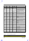
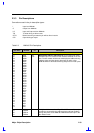
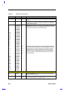
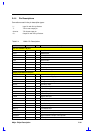
Table 2-3 NM2160 Pin Descriptions
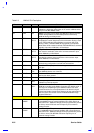
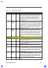
Pin name Number I/O Description
143 FPVEE O
Flat Panel VEE This is used to control the bias power to the
panels
108 FPBACK O
Flat Panel Backlight This is used to control the backlight power
to the panels or as a General Purpose Output Pin as defined by
register CR2F bits 3&2
7
6
5
4
3
2
176
174
172
171
170
169
18
17
16
15
14
13
117
118
119
120
121
122
123
124
126
127
128
129
130
131
135
137
139
140
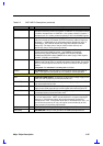
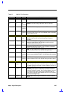
PDATA35
PDATA34
PDATA33
PDATA32
PDATA31
PDATA30
PDATA29
PDATA28
PDATA27
PDATA26
PDATA25
PDATA24
PDATA23
PDATA22
PDATA21
PDATA20
PDATA19
PDATA18
PDATA17/
LCD_ID0
PDATA16/
LCD_ID1
PDATA15/
LCD_ID2
PDATA14/
LCD_ID3
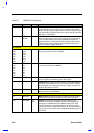
PDATA13
PDATA12
PDATA11
PDATA10
PDATA9
PDATA8
PDATA7
PDATA6
PDATA5
PDATA4
PDATA3
PDATA2
PDATA1
PDATA0
O
I/O
I/O
I/O
I/O
Panel data These pins are used to provide the data interface to
different kinds of panels. The following table shows the functions
of these pins based on the selected panel type
LCD_ID[3..0] pins are general purpose read only bits which can
be used for panel identification. During RESET# these LCD_ID
pins are inputs. The state of these bits are reflected in register
CR2Eh bits 3:0. The state of these bit can also be sampled
anytime on-the-fly through register GR17 bit-3. Internally these
pins are pulled-up, recommended external pull down resistor
value is 22k ohm
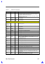
CRT Interface
90 VSYNC O
T/S
CRT Vertical Sync This output is the vertical synchronization
pulse for the CRT monitor
89 HSYNC O
T/S
CRT Horizontal sync This output is the horizontal
synchronization pulse for the CRT monitor