


Major Chips Description 2-23
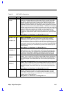
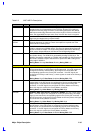
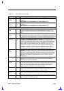
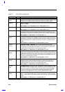
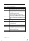
Table 2-2 82371AB Pin Descriptions
Name Type Description
USBP0+,
USBP0–
I/O
SERIAL BUS PORT 0. This signal pair comprises the differential data signal for
USB port 0.
During Reset: High-Z After Reset: High-Z During POS: High-Z
USBP1+,
USBP1–
I/O
SERIAL BUS PORT 1. This signal pair comprises the differential data signal for
USB port 1.
During Reset: High-Z After Reset: High-Z During POS: High-Z
POWER MANAGEMENT SIGNALS
BATLOW#/
GPI9
I
BATTERY LOW. Indicates that battery power is low. PIIX4 can be programmed
to prevent a resume operation when the BATLOW# signal is asserted. If the
Battery Low function is not needed, this pin can be used as a general-purpose
input.
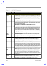
CPU_STP#/
GPO17
O
CPU CLOCK STOP. Active low control signal to the clock generator used to
disable the CPU clock outputs. If this function is not needed, then this signal can
be used as a general-purpose output. For values During Reset, After Reset, and
During POS, see the Suspend/Resume and Resume Control Signaling section.
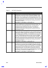
EXTSMI# I/OD
EXTERNAL SYSTEM MANAGEMENT INTERRUPT. EXTSMI# is a falling edge
triggered input to PIIX4 indicating that an external device is requesting the
system to enter SMM mode. When enabled, a falling edge on EXTSMI# results
in the assertion of the SMI# signal to the CPU. EXTSMI# is an asynchronous
input to PIIX4. However, when the setup and hold times are met, it is only
required to be asserted for one PCICLK. Once negated EXTSMI# must remain
negated for at least four PCICLKs to allow the edge detect logic to reset.
EXTSMI# is asserted by PIIX4 in response to SMI# being activated within the
Serial IRQ function. An external pull-up should be placed on this signal.
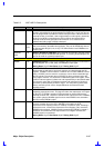
LID/
GPI10
I
LID INPUT. This signal can be used to monitor the opening and closing of the
display lid of a notebook computer. It can be used to detect both low to high
transition or a high to low transition and these transitions will generate an SMI#
if enabled. This input contains logic to perform a 16-ms debounce of the input
signal. If the LID function is not needed, this pin can be used as a general-
purpose input.
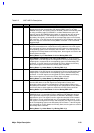
PCIREQ[A:D]# I
PCI REQUEST. Power Management input signals used to monitor PCI Master
Requests for use of the PCI bus. They are connected to the corresponding
REQ[0:3]# signals on the Host Bridge.
PCI_STP#/
GPO18
O
PCI CLOCK STOP. Active low control signal to the clock generator used to
disable the PCI clock outputs. The PIIX4 free running PCICLK input must remain
on. If this function is not needed, this pin can be used as a general-purpose
output. For values During Reset, After Reset, and During POS, see the
Suspend/Resume and Resume Control Signaling section.
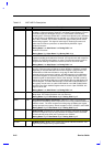
PWRBTN# I
POWER BUTTON. Input used by power management logic to monitor external
system events, most typically a system on/off button or switch. This input
contains logic to perform a 16-ms debounce of the input signal.
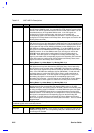
RI#
GPI12
I
RING INDICATE. Input used by power management logic to monitor external
system events, most typically used for wake up from a modem. If this function is
not needed, then this signal can be individually used as a general-purpose input.
RSMRST# I
RESUME RESET. This signal resets the internal Suspend Well power plane
logic and portions of the RTC well logic.