


2-74 Service Guide
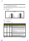
2.9 Ambit DC-AC Inverter
This notebook uses two kinds of DC-AC inverters: One (T62.088.C) is designed for the 13.3-inch
TFT (LG LP133X1) LCD, the other (T62.055.C) for the 12.1-inch TFT (IBM ITSV50D) LCD.
2.9.1 T62.055C
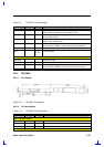
2.9.1.1 Pin Diagram
CN2
CN1
T62.055.C
1
2
21
20
3
2
1
CN3
Figure 2-12 T62.055.C Pin Diagram
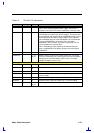
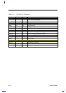
2.9.1.2 Pin Descriptions
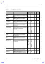
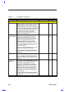
Table 2-9 T62.055.C Pin Descriptions
Pin Name Pin Type Pin No. Descriptions
CN1 connector signals
Vhi
Vlo
O 1
2
This is the High voltage side of the Lamp. (The shorter wire to
lamp connects to this output.
Max lamp start voltage(Vrms): 1300
Typical lamp run voltage @25°C(Vrms): 650
Min open circuit voltage (Vrms): 1100
Max open circuit voltage(Vrms): 1500
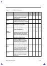
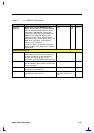
CN2 connector signals
GND GND 1, 6 This the return signal for the input power and control signals and
is an extension of the system ground.
CNTADJ O 2, 9 Contrast adjustment (reserved)
DCIN I 3, 4, 5 This is the input DC voltage to supply the operating power.
Max value: 19VDC
Min value: 7 VDC
BRTADJ O 7 This is an analog signal in the range of 0 to 3 volts to control the
lamp current.
Vbrite = 1 volt, Lamp current = 50%±10% of Max.
Vbrite = 3volts, Lamp current = Max = 4.5mA
PANEL_ON I 8 A control pin to control on/off lamp. This input enable the
inverter operation (Lamp On) when high and disables the inverter
when low. This signal is output from a 3.3V CMOS device.
Max loading = 100uA
Logic Low = 0.8 volts Max.
Logic High =1.8 volts Min.
PWRLED O 12 This signal is an open collector sink signal to drive LED1. The
LED current is limited by a series resistor of 1KΩ.