


9
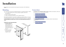
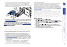
Power supply connection
The SmartView World is supplied with a single power supply and an appropriate
country-specic IEC power lead. The SmartView World does not have an on/off
switch so operation begins as soon as the power supply is connected.
Note: When computers are rst powered on they communicate with any
attached keyboards and mice in order to setup parameters required by their
operating system. It is necessary for the SmartView World to be attached and
powered on during this sequence so that it can give the required responses
and keep track of all modes and settings requested by each of the connected
computers.
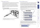
To connect the power supply
1 Connect the low voltage output connector from the power supply unit
to the SmartView World power socket in the lower left corner of the rear
panel.
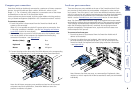
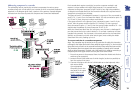
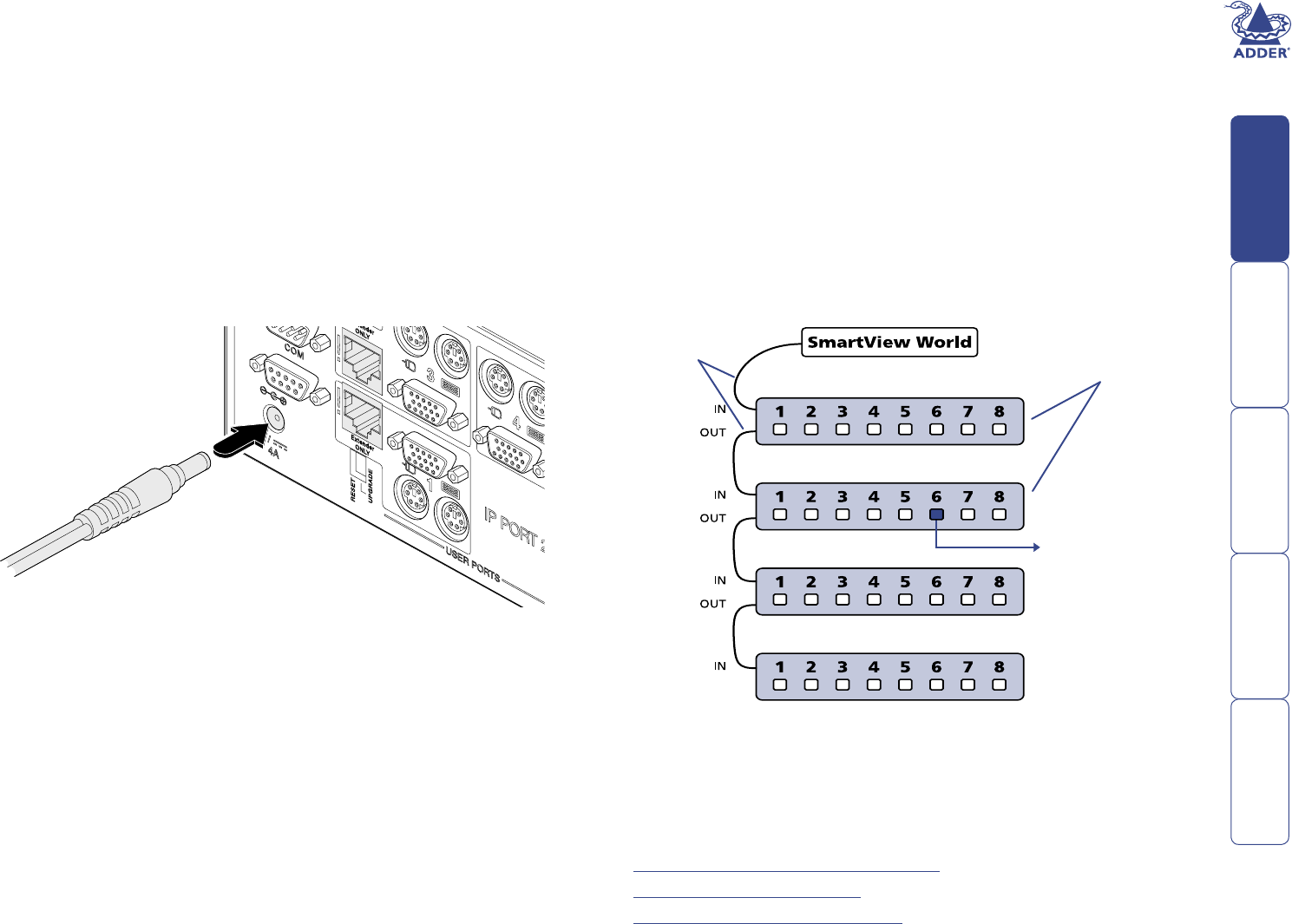
Power switching connections
A key feature of the SmartView World is its ability to remotely control the power
of the computers attached to it. The actual power switching process requires
the use of optional switch boxes available from a number of suppliers (Adder
part number: EPS-S8), however, the SmartView World offers the control port for
these switches and the necessary operational integration within its menu system.
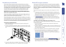
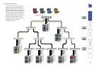
The control connector of the rst power switch is connected, via serial cable,
to the rear panel of the SmartView World. Any additional power switches are
then connected via a ‘daisy-chain’ arrangement to the rst power switch. Each
power switch box is then given a unique address and access to each power port
(8 ports on each power switch box) is gained using a combination of the switch
box address and the port number.
Each power port can then be connected to the power inputs of each computer
and each power switch box then connected to a mains power supply.
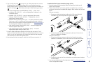
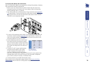
2 Connect the IEC connector of the supplied country-specic power lead to
the socket of the power supply.
3 Connect the power lead to a nearby main supply socket.
IMPORTANT: Power switching devices have a maximum current rating. It is
essential to ensure that the total current drawn by the equipment connected
to the power switching device does not exceed the current rating of the power
switching device. You must also ensure that the current drawn from any mains
socket does not exceed the current rating of the mains socket.
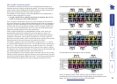
Setting up, conguring and using power switching requires three main steps:
• Connect and address the switch boxes
• Congure the power strings
• Operate remote power switching
Power to computer
Box 2, port 6 - address: 26
Box 1
Box 2
Box 3
Box 4
Power
switch
boxes
‘Daisy-chain’
control
connections