


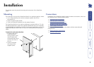
13
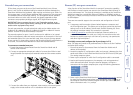
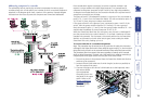
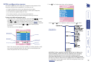
Addressing computers in a cascade
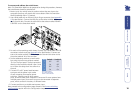
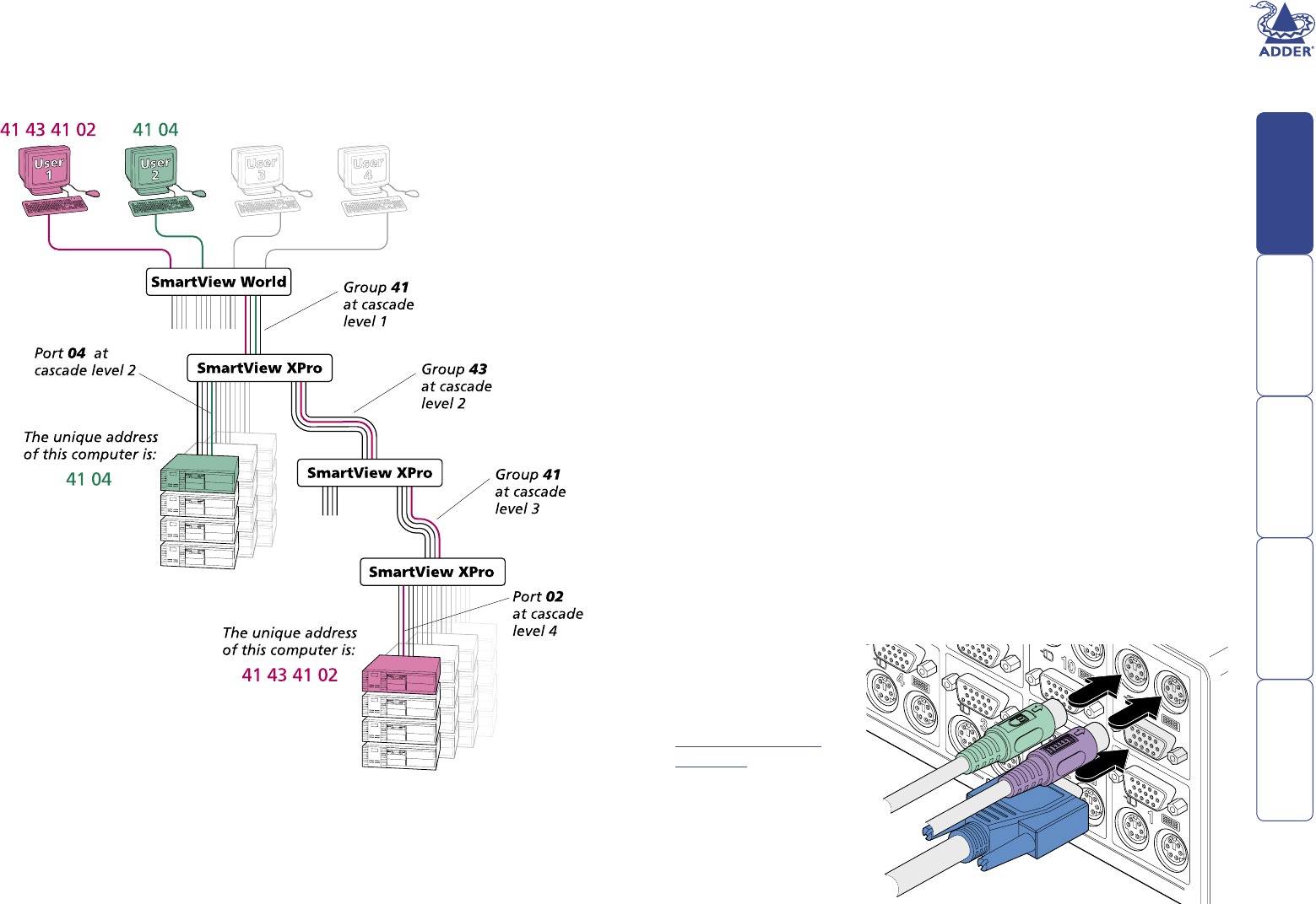
The addressing format used by the switches incorporates the various group
numbers along with a nal specic port number to which a required computer is
attached. In the diagram given here, a portion of the previous cascade diagram
indicates how the routes to particular computers are formed and addressed.
Each cascade level requires two digits, hence the computer marked in red
requires a unique address with eight digits because it is at cascade level 4,
compared to the green computer at level 2 with its four digit unique address.
A computer connected directly to the SmartView World at the top level would
simply have a two digit port number.
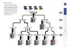
The group at level 2 is numbered 43 because it is a group of four, connected to
ports 9, 10, 11 and 12 on the SmartView World. If it was connected to ports 13,
14, 15 and 16, then the group number would be 44.
If the group at level 3 was a group of two, connected to ports 1 and 2 of the
switch, then the group number would be 21. Similarly, if it was a group of
three connected to ports 1, 2 and 3, then the group number would be 31 – this
would make the address of the red computer: 41 43 31 02.
While the SmartView World has four user ports, one of those is a dedicated IP
port that cannot be fed to a switch above (i.e. it can feed a maximum of three
cascade links upwards). For this reason, the natural position for the SmartView
World is as the master unit with other switch types, most suitably the Adder
SmartView XPro units, feeding up into it.
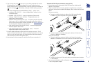
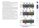
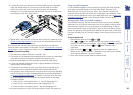
To connect switches in a cascade arrangement
Note: This procedure may be carried out in any order but for clarity this instruction
will begin at the higher level switch (here called the upper switch), i.e. the one that is
being fed into by a switch at the cascade level below (here called the lower switch).
The procedure given here remains the same regardless of exactly which cascade
levels are being connected. The basic rule is that each link is made by connecting a
computer port of the upper switch to a user port of the lower switch.
1 Ensure that power is disconnected from the SmartView World and all other
switches to be connected.
2 Locate sufcient KVM cable sets of similar lengths (as short as possible) to
form the required link group.
3 Connect the plugs at one end of a KVM cable set to the keyboard, video
and mouse sockets
of an appropriate
Computer port on the
rear panel of the upper
switch. Refer to the
Group numbering
diagrams for the
correct link group
boundaries.