


12
How cascade connections operate
The method for cascading switching units is straightforward and requires no
hardware settings or lengthy conguration process. This is due to the intelligent
communication system employed by all Adder SmartView-family switches that
allows them to locate each other and share information.
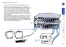
The method of linking switches is the same regardless of the cascade level, or
number of devices attached. Put simply:
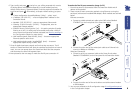
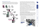
• A single cascade link is made by connecting a computer port of one
switch to a user port of the switch below it.
Such a single link would allow just one user from the higher switch to access
any of the computers (or other switches) attached to the lower one. However, a
single link can cause a bottleneck for multi-user systems, so it is commonplace
to make more than one cascade link between switches. Multiple cascade links
(up to four on most switches) allow up to four users to simultaneously access
computers situated anywhere within the cascade tree.
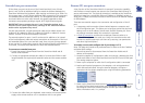
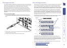
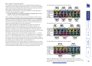
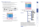
When multiple cascade links are made between switches, each switch will
automatically recognise the multiple links and treat them as a group. The
links within a group will then be allocated to users according to their general
availability in that group, not as specic individual lines. To do this, each link
group has an access number, which is determined by the quantity of links within
that group and to which ports they are connected on the switch.
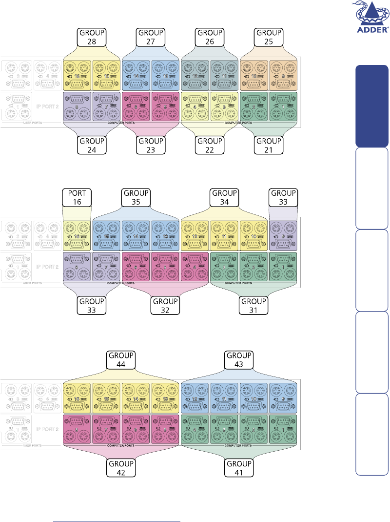
For instance, a group of four links connected to computer ports 1, 2, 3 and 4
of a switch would always be known as 41, the next group of four connected to
ports 5, 6, 7 and 8 would always carry the number 42, and so on. The same is
also true for two and three link groups which have their own specic numbers.
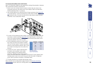
The diagrams here summarise the ports to which groups must be connected and
the resulting group numbers attained in the positions here
ð
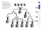
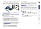
The central purpose of the link group system is that each user can use a unique
address to locate a particular computer, however, as with the Internet, the route
to get there could be slightly different each time. This avoids any route blocking
that could easily be caused by other users occupying any specic link lines.
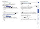
Port boundaries and numbering for two link groups
Port boundaries and numbering for three link groups
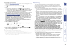
Port boundaries and numbering for four link groups
Note: Link groups of twos, threes and fours may be mixed on one switch
providing each size of group lies within the appropriate port boundaries shown
above - see Tips for successful cascading for more details.