


7
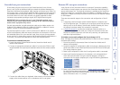
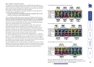
Remote (IP) user port connections
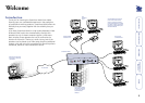
A key function of the SmartView World is its remote IP connection capability,
which allows universal remote user access to the SmartView World through a
secure web browser link. The physical connection is available at the SmartView
World front panel via a twisted pair Ethernet (10Mbps or 100Mbps) socket or
serial port (115Kbps) connector, the latter of which can drive an external modem
or ISDN adapter.
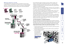
There are two essential stages to the connection and conguration of the IP
port:
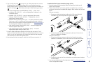
• A temporary serial connection (shown below) between a computer and
the IP conguration port. This allows you to congure various key low level
settings such as the IP address, Subnet mask, Default Gateway, etc. Once
the settings have been made, this connection is removed.
• A nal IP connection to either the twisted pair Ethernet socket or a
modem/ISDN adapter to the serial
port. Using this connection and a web
browser on another system you can then set up security, user permissions
and other high level options.
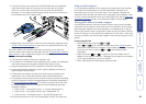
To initially connect and congure the IP port (stage 1 of 2)
Note: This stage only needs to be performed once in order to set the IP address
and other basic settings.
1 Ensure that power is disconnected from the SmartView World and all
devices to be attached.
2 Locate the supplied ‘IP conguration cable’ and connect it between the front
panel serial socket of the SmartView World and the RS232 serial (COM) port
of a nearby computer system.
3 Power up the computer to which the IP conguration cable is connected.
4 Load a serial terminal program on the computer, such as Hyperterminal
within Microsoft Windows. Using the terminal program, congure a
connection via the chosen computer port using the following parameters:
Data speed 115200
Data bits 8
Parity None
Stop bits 1
Flow control None
5 Power up the SmartView World (see the Power supply connection section)
(or press the front panel reset button) and immediately press the key on
the computer. Within the terminal program window you should see some
device information and a ‘=>’ prompt.
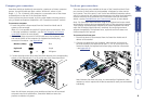
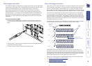
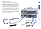
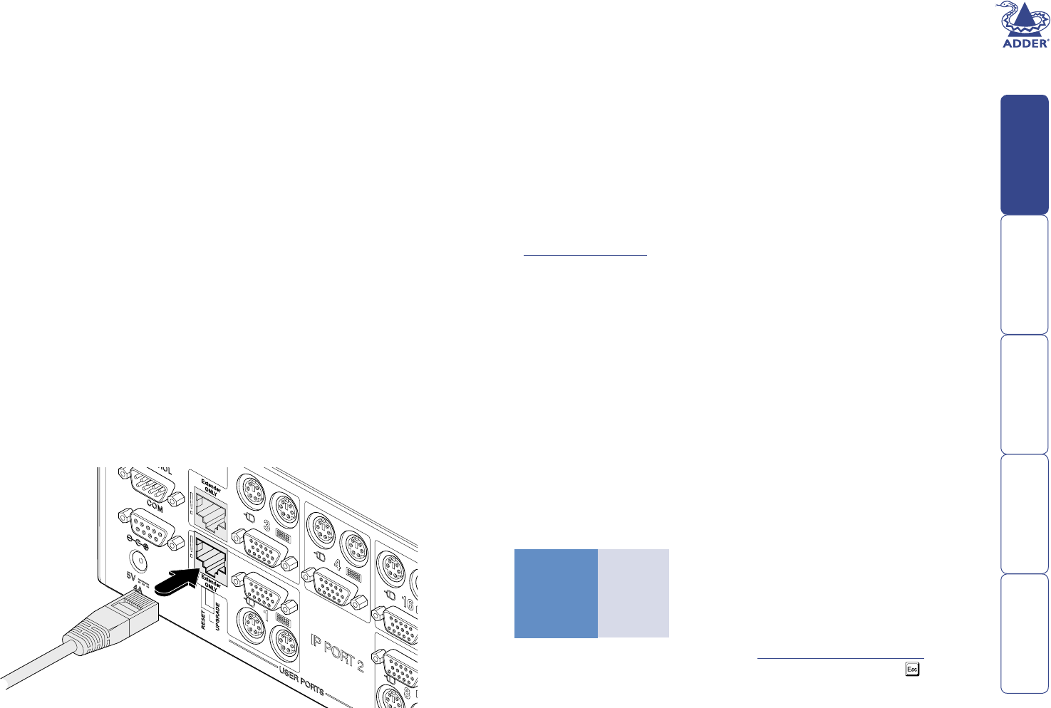
Extended user port connections
Of the three user ports at the rear of the SmartView World, two of these
(ports 1 and 3) offer an additional ability to extend the distance between the
SmartView World and the keyboard, video monitor and mouse up to 200m. For
this purpose, ports 1 and 3 feature additional RJ45 connectors of the type used
for standard Ethernet twisted pair cabling. This arrangement allows standard
structured cable runs to be used, however, the signals presented at these
connectors are proprietary analogue signals, NOT digital Ethernet signals.
IMPORTANT: Never connect the port 1 and 3 extender sockets to an
Ethernet hub or other digital device, damage to the SmartView World
and/or other equipment may result.
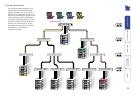
For each port extender, a single twisted pair cable and an Adder receiver unit
(AdderLink XR, AdderLink Silver XR, AdderLink Gold XR or AdderLink X-series
remote - but NOT X-Series Gold remote) is required.
The extender options for ports 1 and 3 can be used in addition to (or instead
of) the local keyboard, video and mouse connections on those ports. If the local
and extended options for a port are both used, then only one set may operate
at any one time. In these cases, access to the SmartView World is arbitrated on a
‘rst-come, rst-served’ basis between the local and extended devices.
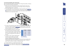
To connect an extended user port
1 Ensure that power is disconnected from the SmartView World and all
devices to be attached.
2 Connect an appropriate twisted pair cable (of no more than 200m in total
length) between the required port extender socket and the remote receiver
unit.
3 Connect the cables from your keyboard, video monitor, mouse and power
supply to the remote receiver unit in accordance with its user guide.