


24
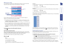
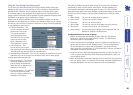
Editing power strings
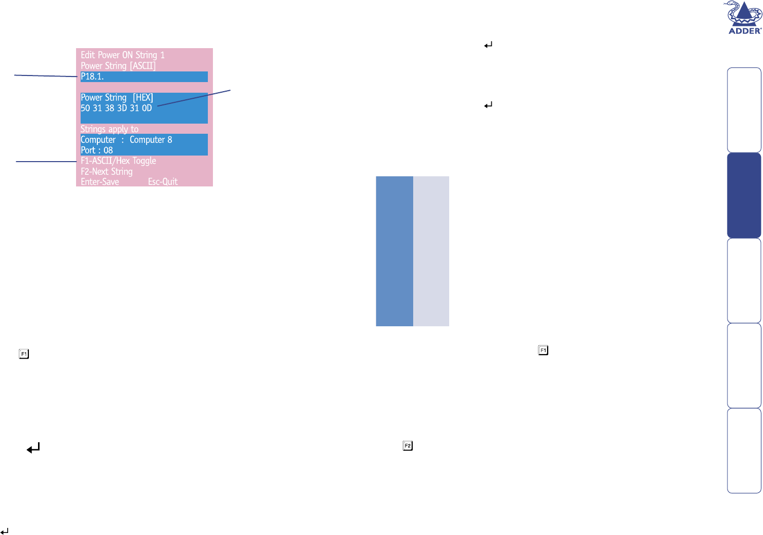
The string editing screen has two editing areas where you can enter and view
the power switch code as either: ASCII characters or HEX values.
Example 1
To switch ON port 5 of switch box 2, the ASCII and HEX codes would be as follows:
• ASCII string: P25=1
• HEX characters: 50 32 35 3D 31 0D
Example 2
To switch OFF port 8 of switch box 3, the ASCII and HEX codes would be as follows:
• ASCII string: P38=0
• HEX characters: 50 33 38 3D 30 0D
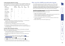
ASCII characters and equivalent HEX codes
The table given here shows the various ASCII characters that you will need along
with their HEX equivalents:
ASCII Hex
P 50
1 31
2 32
3 33
4 34
5 35
6 36
7 37
8 38
= 3D
Enter 0D
Note: Remember, you cannot add the ‘Enter’ command within the ASCII area,
you must change to the HEX area (using ) and type the equivalent code ‘0D’.
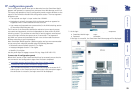
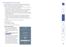
Creating power port groups
Where multiple power inputs to a server require simultaneous switching, up to
four ports can be formed into a power port group.
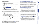
To add/edit further power strings in order to switch extra ports
1 Edit the rst power ON string as described above.
2 Press to edit an additional power ON string. Input the appropriate switch
box number and port address for the next power port.
3 Repeat step 2 for each power port that must be simultaneously switched.
4 Repeat all of these steps for the corresponding power OFF strings.
Note: The second, third and fourth strings are actually sent in quick succession.
If required, this feature could be used to create one long string for a single port.
The two areas are linked so that as you change one, the other changes in
response. The ASCII edit area has two limitations:
• The ASCII edit area cannot display the ‘=’ character, and represents it with
a fullstop when you type ‘=’. However, even though it is not displayed, the
character is correctly stored and used.
• You cannot add the ‘Enter’ character (which is needed at the end of the line)
within the ASCII edit box. This must be added within the HEX area, using
the code ‘0D’. The ‘Enter’ character is also represented in the ASCII area by
a fullstop, so the HEX area provides the truest representation of the string
contents.
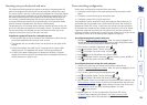
To change between the ASCII and HEX edit areas
• Press
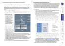
The structure of power strings
Note: The settings given below are for the EPS-S8 power switch - other power
switches may require different settings. Please refer to Adder for advice on how
to congure the SmartView World to control other power switches.
The ASCII structure of each string (OFF and ON) is as follows:
Pxy=z
Where:
x is the switch box number,
y is the power port number,
z is ‘0’ for OFF or ‘1’ for ON, and
is the Enter (or Carriage return) character (0D in Hex).
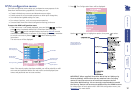
ASCII editing
area
HEX editing
area
Press F1 to change
between the ASCII
and HEX editing
areas