


33
HT
Operation
Powering on
The SmartView World does not have a power switch, so whenever power is
applied via the supplied adapter, the unit is operational. A green indicator on the
front panel (labelled ‘Power’) shows power input status.
Note: Before applying power to the SmartView World, ensure that the two
option switches at the rear panel are both set to the OFF (up) position.
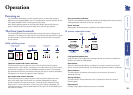
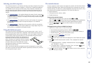
The front panel controls
The SmartView World front panel provides a range of buttons, indicators and
connectors. The items on the left side of the front panel are linked with the KVM
switching aspects, while the right-side are solely concerned with the remote IP
access features.
KVM switching items
User port activity indicators
These four red indicators provide conrmation that keyboard and mouse activity
is being detected from each of the four user ports.
Power indicator
Glows green whenever power is applied to the SmartView World.
IP remote-connection items
Computer button and
numeric indicator
User button and
numeric indicator
User port activity
indicators
Power
indicator
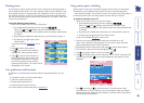
Computer button and numeric indicator
These items allow you to select any one of the SmartView World’s sixteen
computer ports. As the button is pressed, the number shown by the red numeric
indicator will increment to the next available computer channel. The computer
port selected will then be connected to the user port that is currently selected by
the adjacent user button and green numeric indicator.
User button and numeric indicator
These items allow you to select any one of the SmartView World’s four user
ports. With each press of the button, the number displayed by the green
numeric indicator will advance from port 1 through to port 4 and then loop
back to port 1. At the same time, as each user port number is displayed, the
computer port that is currently associated with that port will be indicated by the
red numeric indicator.
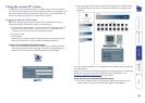
Conguration/modem port
Used to make initial conguration settings and also to connect the SmartView
World to a modem or ISDN adapter.
Reset button
When this small recessed button is pressed, a full reset is carried out on the IP
section of the SmartView World. The KVM switching section remains unaffected.
Status indicator
This red indicator illuminates continuously to show that the IP section is
operating correctly.
Activity indicator
This red indicator ashes whenever trafc is detected on either the serial or
Ethernet ports.
Ethernet port
Provides a high speed connection point to IP networks.
Conguration/
modem port
Status and activity
indicators
Reset
button
Ethernet
port