


10
To connect and address the switch boxes
Note: The SmartView World can be powered on during this procedure, however,
the switch boxes should be switched off.
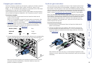
1 Mount up to four switch boxes in positions where they are close to the
computers that they will control and not too distant from the SmartView
World (preferably within 2.5 metres).
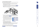
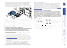
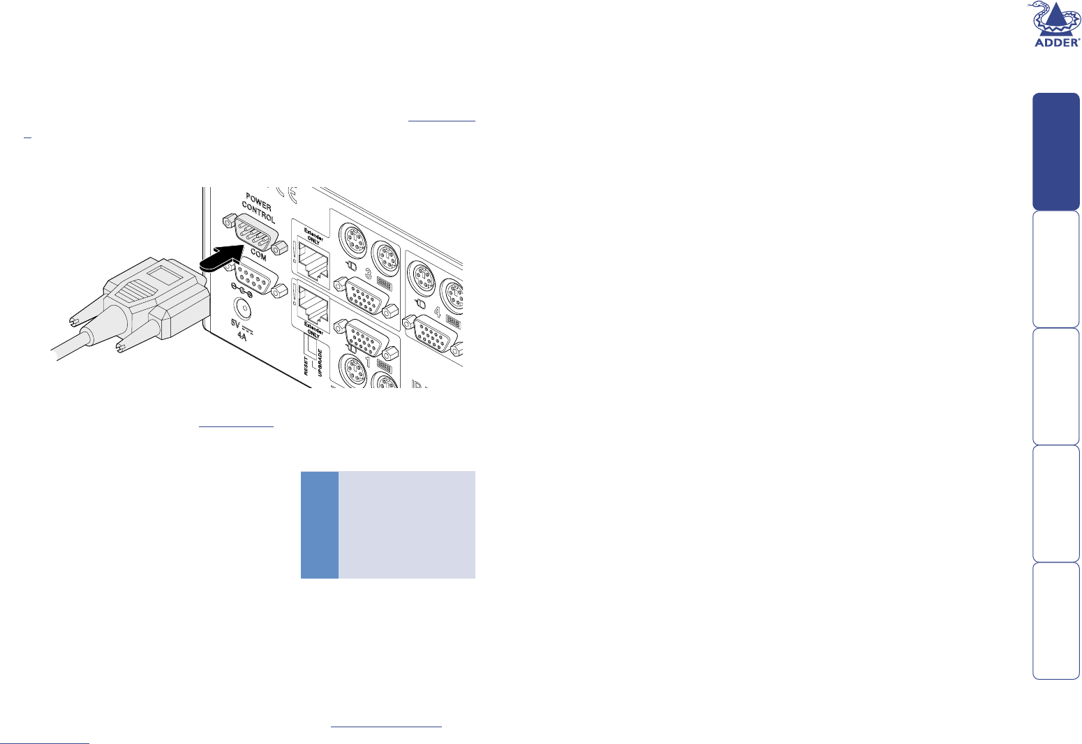
2 Use a serial cable with an RJ9 and a 9-pin D-type connector (see Appendix
4 for specication). Connect the RJ9 plug to the socket marked ‘IN’ on
the rst switch box. Connect the other end to the socket marked ‘POWER
CONTROL’ on the SmartView World.
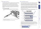
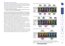
Box Switch 1 Switch 2
1 Off Off
2 On Off
3 Off On
4 On On
Off = switch upwards
On = switch downwards
Switch 1 is on the left side
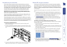
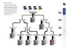
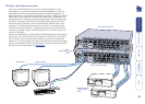
3 For each of the remaining switch boxes (if used), use a serial cable with RJ9
connectors at both ends (see Appendix 4 for specication). Connect one
end to the socket marked ‘OUT’ of the previous box and the other end to
the socket marked ‘IN’ of the next box.
4 Set the addressing switches on each switch
box using the two micro switches marked
‘Slct’ on the front panel. The box connected
directly to the SmartView World is Box 1 and
so on down the daisy-chain line to Box 4 at
the end.
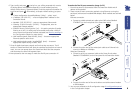
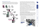
5 Connect IEC to IEC power leads between
each port and the power input socket
of each computer that requires power
switching. Carefully note to which power
ports, on which boxes, each computer is connected. If server systems have
multiple power inputs, then each input must be connected via separate
ports, which can be on the same, or different boxes.
6 Connect each box to a suitable mains power input.
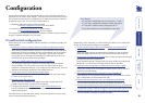
Now proceed to the conguration stage covered in the Power switching
conguration section within the Conguration chapter.