


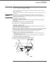
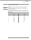
To test the CRT monitor signals
Refer to chapter 6, "Replacing Assemblies," for instructions to remove or replace covers and
assemblies.
WARNING
Hazard voltages exist on the power supply, the CRT, and the CRT driver board. This
procedure is to be performed by service-trained personnel aware of the hazards involved,
such as fire and electrical shock.
1
Remove the cover of the instrument.
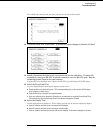
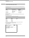
2 Check the CRT monitor input cable for the signals and the power supplies listed in
the table below. The cable is the wide ribbon cable connecting the monitor to the
acquisition board.
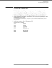
CRT Monitor Cable Signals
Pin Signal Pin Signal
1NC2+12 V
3 Ground 4 Ground
5 +12 V 6 Ground
7 +12 V 8 Ground
9 +12 V 10 HSYNC
11 VSYNC 12 +12 V
13 Ground 14 Ground
15 Ground 16 Video
17 Ground 18 NC
19 Ground 20 NC
Troubleshooting
To test the CRT monitor signals
5–23