


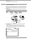
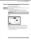
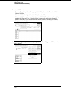
c Press the Trigger key. Make sure pattern term a is "A". If not, select the field next to
"a" under the label Lab1. Type "A" then press the Select key.
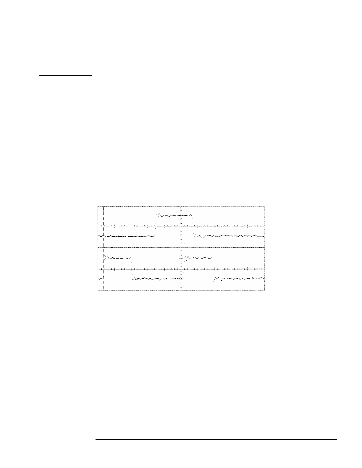
Verify the test signal
1 Check the clock period. Using the oscilloscope, verify that the clock period is 20 ns,
+0 ps or −250 ps.
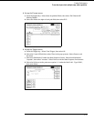
a In the oscilloscope Timebase menu, select Sweep Speed 4.00 ns/div.
b Select Delay. Using the oscilloscope knob, position the clock waveform (Channel 2)
so that a rising edge appears at the left of the display.
c In the oscilloscope Measure menu, select Measure Chan 2, then select +Width. If the
positive-going pulse width is more than 20.000 ns, go to step d. If the pulse width is
less than or equal to 20.000 ns, go to step 2.
d In the oscilloscope Measure menu, select -Width. If the negative-going pulse width is
less than or equal to 20.000 ns but greater than 19.75 ns, go to step 2.
e Decrease the pulse generator Period in 100 ps increments until the oscilloscope
Measure +Width or Measure -Width reads less than or equal to 20.000 ns, but greater
than 19.75 ns.
Testing Performance
To test the single-clock, multiple-edge, state acquisition
3–49