


To test the multiple-clock, multiple-edge, state acquisition
Testing the multiple-clock, multiple-edge, state acquisition verifies the performance
of the following specifications:
• Minimum master to master clock time.
• Maximum state acquisition speed.
• Setup/Hold time for multiple-clock, multiple-edge, state acquisition.
• Minimum clock pulse width.
This test checks data using multiple clocks at three selected setup/hold times.
Equipment Required
Equipment Critical Specifications Recommended
Model/Part
Pulse Generator 100 MHz 3.5 ns pulse width, < 600 ps rise time Agilent 8131A option 020
Digitizing Oscilloscope
≥ 6 GHz bandwidth, < 58 ps rise time
Agilent 54121T
Adapter SMA(m)-BNC(f) Agilent 1250-1200
SMA Coax Cable (Qty 3) 18 GHz bandwidth Agilent 8120-4948
BNC Cable BNC(m)(m) 48 in. >2 GHz bandwidth Agilent 8120-1840
Coupler BNC(m)(m) Agilent 1250-0216
BNC Test Connector,
6x2 (Qty 4)
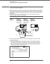
Set up the equipment
1 Turn on the equipment required and the logic analyzer. Let them warm up for
30 minutes before beginning the test if you have not already done so.
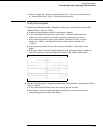
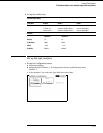
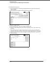
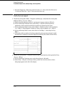
2 Set up the pulse generator.
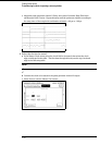
a Set up the pulse generator according to the following table.
Pulse Generator Setup
Channel 1 Channel 2 Period
Delay: 0 ps Doub: 20.0 ns 40 ns
Width: 4.5 ns Width: 3.5 ns
High: −0.9 V High: −0.9 V
Low: −1.7 V Low: −1.7 V
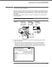
b Disable the pulse generator channel 2 COMP (with the LED off).
3–34