


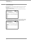
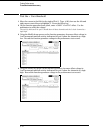

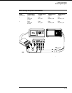
3 Set up the oscilloscope.
Oscilloscope Setup
Time Base Display Delta V Delta T
Time/Div: 1.00 ns/div mode: avg V markers on T markers on
delay: 17.7000 ns # of avg: 16 marker 1 position: Chan 1 start on: Pos Edge 1
screens: dual marker 2 position: Chan 2 stop on: Pos Edge 1
Channel
Channel 1 Channel 2
Display
on on
Probe Atten
20.00 20.00
Volts/Div
400 mV 400 mV
Offset
−1.3000 V −1.3000 V
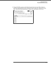
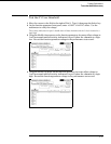
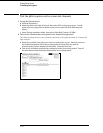
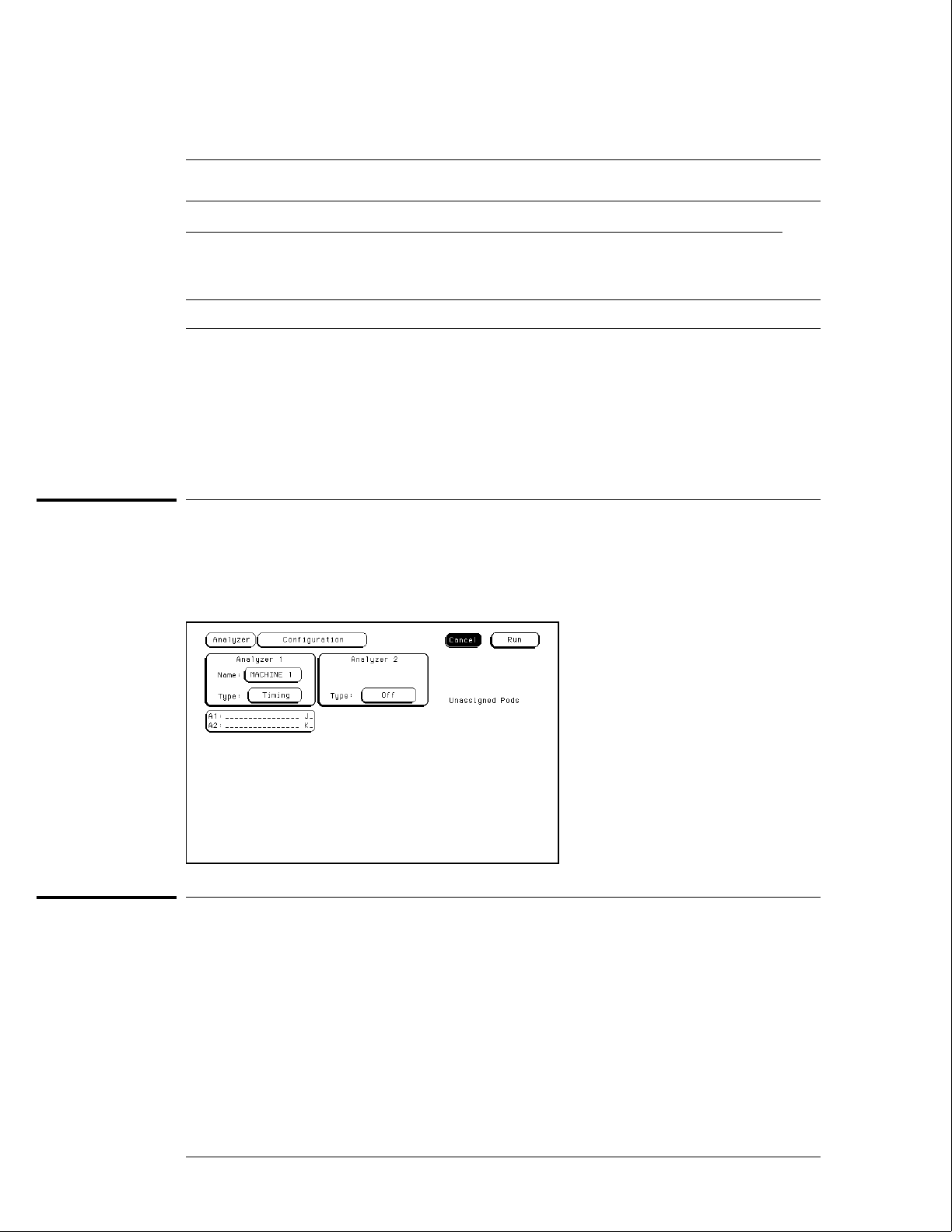
Set up the logic analyzer
1 Press the Config key. Assign all pod fields to Machine 1. To assign the pod fields,
select the pod fields, then select Machine 1 in the pop-up menu.
2 In the Analyzer 1 box, select the Type field. Select Timing in the pop-up menu.
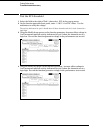
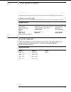
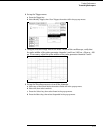
Connect the logic analyzer
1 Using SMA cables, connect the oscilloscope to the pulse generator channel 1
Output, channel 2 Output, and Trig Output.
2 Using the 6-by-2 test connectors, connect the first combination of logic analyzer
clock and data channels listed in the table to the pulse generator.
You will repeat this test for the remaining combinations.
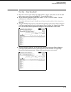
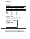
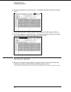
Testing Performance
To test the glitch capture
3–18