


Centronix
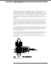
The logic analyzer interfaces with Centronix (parallel printer) communication lines
through a standard 25 pin D connector. The logic analyzer is compatible with
Centronix protocol. BUSY is used to indicate when data can be transfered from the
logic analyzer to the printer. DATASTROBE is used to synchronize data
transmissions. Pin outs of the Centronix connector are listed in the following table.
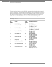
Centronix Signal Definitions
Pin
Number
Function Centronix
Standard
1 Synchronous signal that is used for data transfer STROBE
2 Logic analyzer data (LSB) DATA0
3 Logic analyzer data DATA1
4 Logic analyzer data DATA2
5 Logic analyzer data DATA3
6 Logic analyzer data DATA4
7 Logic analyzer data DATA5
8 Logic analyzer data DATA6
9 Logic analyzer data (MSB) DATA7
10 Signal used to indicate that data has been received ACKNLG
11 Signal used to indicate that the printer is busy BUSY
12 Signal used to indicate that the printer is out of paper PERROR
13 Signal that indicates that the printer is on-line SELECT
14 Signal used to select the autofeed function AUTOFD
15 Signal that indicates command or data error FAULT
16 Signal used to initialize the printer INIT
17 Signal used to select the direction of the bi-directional bus SELECTIN
18 - 25 Ground GND
8–17