


To make the test connectors
The test connectors connect the logic analyzer to the test equipment.
Materials Required
Description Recommended Part Qty
BNC (f) Connector Agilent 1250-1032 5
100 Ω 1% resistor
Agilent 0698-7212 8
Berg Strip, 17-by-2 1
Berg Strip, 6-by-2 4
20:1 Probe Agilent 54006A 2
Jumper wire
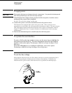
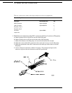
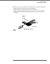
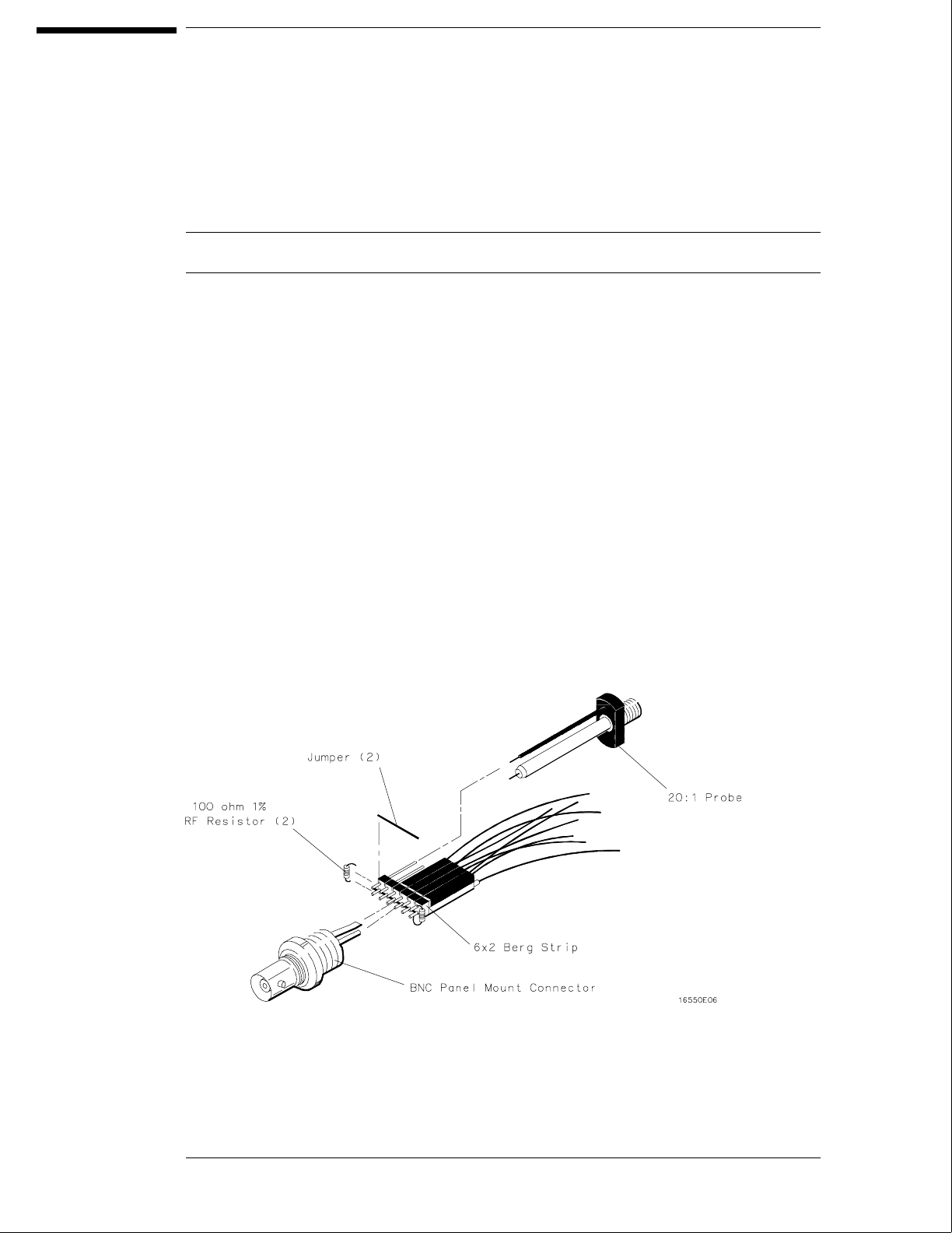
1 Build four test connectors using BNC connectors and 6-by-2 sections of Berg strip.
a Solder a jumper wire to all pins on one side of the Berg strip.
b Solder a jumper wire to all pins on the other side of the Berg strip.
c Solder two resistors to the Berg strip, one at each end between the end pins.
d Solder the center of the BNC connector to the center pin of one row on the Berg strip.
e Solder the ground tab of the BNC connector to the center pin of the other row on the
Berg strip.
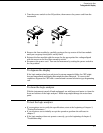
f On two of the test connectors, solder a 20:1 probe. The probe ground goes to the
same row of pins on the test connector as the BNC ground tab.
3–6