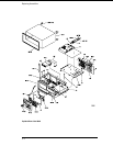
To remove and replace the rear panel assembly
1 Using previous procedures, remove the following assemblies:
•
Handle
•
Rear Feet
•
Cover
2
Remove the switch actuator cable from the line filter according to "To remove and
replace the switch actuator assembly."
3 Disconnect the BNC In/Out and fan cables on the Main Circuit board.
4 Disconnect the RS-232C an GPIB cables from the Main Circuit board.
5 Remove the two standoffs connecting the parallel printer connector socket to the
rear panel.
6 Remove the two screws connecting the keyboard connector socket to the rear panel.
7 Remove the six rear panel screws.
8 Lift the rear panel away from the chassis.
9 Reverse this procedure to install the rear panel.
Check that the following assemblies are properly installed before installing the rear panel:
•
Monitor
•
Main Circuit Board
When installing the rear panel, check that the connectors on the main circuit board are lined
up with the corresponding holes in the rear panel.
Replacing Assemblies
To remove and replace the rear panel assembly
6–9


