AMD Geode™ SC1200/SC1201 Processor Data Book 107
SuperI/O Module
32579B
5.5.2.4 Timekeeping
Data Format
Time is kept in BCD or binary format, as determined by bit
2 (DM) of Control Register B (CRB), and in either 12 or 24-
hour format, as determined by bit 1 of this register.
Note: When changing the above formats, re-initialize all
the time registers.
Daylight Saving
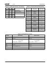
Daylight saving time exceptions are handled automatically,
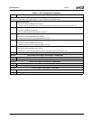
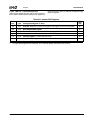
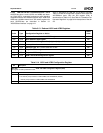
as described in Table 5-20 on page 111.
Leap Years
Leap year exceptions are handled automatically by the
internal calendar function. Every four years, February is
extended to 29 days.
Updating
The time and calendar registers are updated once per sec-
ond regardless of bit 7 (SET) of CRB. Since the time and
calendar registers are updated serially, unpredictable
results may occur if they are accessed during the update.
Therefore, you must ensure that reading or writing to the
time storage locations does not coincide with a system
update of these locations. There are several methods to
avoid this contention.
Method 1
1) Set bit 7 of CRB to 1. This takes a “snapshot” of the
internal time registers and loads them into the user
copy registers. The user copy registers are seen when
accessing the RTC from outside, and are part of the
double buffering mechanism. You may keep this bit set
for up to 1 second, since the time/calendar chain con-
tinue to be updated once per second.
2) Read or write the required registers (since bit 1 is set,
you are accessing the user copy registers). If you per-
form a read operation, the information you read is cor-
rect from the time when bit 1 was set. If you perform a
write operation, you write only to the user copy regis-
ters.
3) Reset bit 1 to 0. During the transition, the user copy
registers update the internal registers, using the dou-
ble buffering mechanism to ensure that the update is
performed between two time updates. This mecha-
nism enables new time parameters to be loaded in the
RTC.
Method 2
1) Access the RTC registers after detection of an Update
Ended interrupt. This implies that an update has just
been completed and 999 msec remain until the next
update.
2) To detect an Update Ended interrupt, you may either:
— Poll bit 4 of CRC.
— Use the following interrupt routine:
– Set bit 4 of CRB.
– Wait for an interrupt from interrupt pin.
– Clear the IRQF flag of CRC before exiting the
interrupt routine.
Method 3
Poll bit 7 of CRA. The update occurs 244 μs after this bit
goes high. Therefore, if a 0 is read, the time registers
remain stable for at least 244 μs.
Method 4
Use a periodic interrupt routine to determine if an update
cycle is in progress, as follows:
1) Set the periodic interrupt to the desired period.
2) Set bit 6 of CRB to enable the interrupt from periodic
interrupt.
3) Wait for the periodic interrupt appearance. This indi-
cates that the period represented by the following
expression remains until another update occurs:
[(Period of periodic interrupt / 2) + 244 μs]
5.5.2.5 Alarms
The timekeeping function can be set to generate an alarm
when the current time reaches a stored alarm time. After
each RTC time update (every 1 second), the seconds, min-
utes, hours, date of month and month counters are com-
pared with their corresponding registers in the alarm
settings. If equal, bit 5 of CRC is set. If the Alarm Interrupt
Enable bit was previously set (CRB bit 5), interrupt request
pin is also active.
Any alarm register may be set to “Unconditional Match” by
setting bits [7:6] to 11. This combination, not used by any
BCD or binary time codes, results in a periodic alarm. The
rate of this periodic alarm is determined by the registers
that were set to “Unconditional Match”.
For example, if all but the seconds and minutes alarm reg-
isters are set to “Unconditional Match”, an interrupt is gen-
erated every hour at the specified minute and second. If all
but the seconds, minutes and hours alarm registers are set
to “Unconditional Match”, an interrupt is generated every
day at the specified hour, minute and second.


