AMD Geode™ SC1200/SC1201 Processor Data Book 157
Core Logic Module
32579B
6.2.7.1 I/O Port 092h System Control
I/O Port 092h allows for a fast keyboard assertion of an
A20# SMI and a fast keyboard CPU reset. Decoding for this
register may be disabled via F0 Index 52h[3].
The assertion of a fast keyboard A20# SMI is controlled by
either I/O Port 092h or by monitoring for the keyboard com-
mand sequence (see Section 6.2.8.1 "Fast Keyboard Gate
Address 20 and CPU Reset" on page 157). If bit 1 of I/O
Port 092h is cleared, the Core Logic module internally
asserts an
A20M#, which in turn causes an SMI to the
GX1 module. If bit 1 is set, A20M# is internally de-
asserted, again causing an SMI.
The assertion of a fast keyboard reset (WM_RST SMI) is
controlled by bit 0 in I/O Port 092h or by monitoring for the
keyboard command sequence (write data = FEh to I/O port
64h). If bit 0 is changed from 0 to 1, the Core Logic module
generates a reset to the GX1 module by generating a
WM_RST SMI. When the WM_RST SMI occurs, the BIOS
jumps to the Warm Reset vector. Note that Warm Reset is
not a pin, it is under SMI control.
6.2.7.2 I/O Port 061h System Control
Through I/O Port 061h, the speaker output can be enabled,
the status of IOCHK# and SERR# can be read, and the
state of the speaker data (Timer2 output) and refresh tog-
gle (Timer1 output) can be read back. Note that NMI is
under SMI control. Even though the hardware is present,
the IOCHK# ball does not exist. Therefore, an NMI from
IOCHK# can not happen.
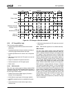
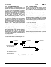
6.2.7.3 SMI Generation for NMI
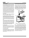
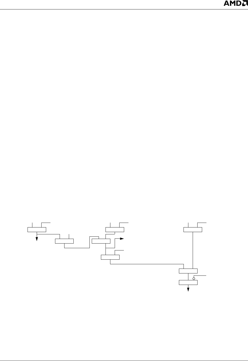
Figure 6-10 shows how the Core Logic module can gener-
ate an SMI for an NMI. Note that NMI is not a pin.
6.2.8 Keyboard Support
The Core Logic module can actively decode the keyboard
controller I/O Ports 060h, 062h, 064h and 066h, and gener-
ate an LPC bus cycle. Keyboard positive decoding can be
disabled if F0 Index 5Ah[1] is cleared (i.e., subtractive
decoding enabled).
6.2.8.1 Fast Keyboard Gate Address 20 and CPU
Reset
The Core Logic module monitors the keyboard I/O Ports
064h and 060h for the fast keyboard A20M# and CPU reset
control sequences. If a write to I/O Port 060h[1] = 1 after a
write takes place to I/O Port 064h with data of D1h, then
the Core Logic module asserts the A20M# signal. A20M#
remains asserted until cleared by any one of the following:
• A write to bit 1 of I/O Port 092h.
• A CPU reset of some kind.
• A write to I/O Port 060h[1] = 0 following a write to I/O
Port 064h with data of D1h.
The fast keyboard A20M# and CPU reset can be disabled
through F0 Index 52h[7]. By default, bit 7 is set, and the
fast keyboard A20M# and CPU reset monitor logic is
active. If bit 7 is clear, the Core Logic module forwards the
commands to the keyboard controller.
By default, the Core Logic module forces the de-assertion
of A20M# during a warm reset. This action may be dis-
abled if F0 Index 52h[4] is cleared.
Figure 6-10. SMI Generation for NMI
PERR#
IOCHK#
F0 Index 04h[6]
SERR#
F0 Index 04h[8]
F0 Index 40h[1]
I/O Port 061h[2]
I/O Port 061h[3]
I/O Port 070h[7]
Parity Errors
AND
System Errors
NMI
SMI
F0 Index 04h: PCI Command Register
Bit 6 = PE (PERR# Enable)
Bit 8 = SE (SERR# Enable)
F0 Index 40h: PCI Function Control Register 1
Bit 1 = PES (PERR# Signals SERR#)
I/O Port 061h: Port B
Bit 2 = ERR_EN (PERR#/SERR# Enable)
Bit 3 = IOCHK_EN (IOCHK Enable)
AND AND
AND
AND
OR
AND
OR
I/O Port 070h: RTC Index Register (WO)
Bit 72 = NMI (NMI Enable)
NMI
(No External Connection)


