348 AMD Geode™ SC1200/SC1201 Processor Data Book
Video Processor Module - Video Processor Registers - Function 4
32579B
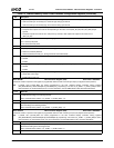
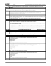
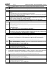
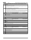
Offset 78h-7Bh Alpha Window 2 Color Register (R/W) Reset Value: 00000000h
31:25 Reserved.
24 ALPHA2_COLOR_REG_EN (Alpha Window 2 Color Register Enable). Enable bit for the color key matching in Alpha
Window 2.
0: Disable. Where there is a color key match, graphics and video are alpha-blended.
1: Enable. If this bit is enabled and the alpha window is enabled, then where there is a color key match, the color value (in
bits [23:0], ALPHA2_COLOR_REG) is displayed.
23:0 ALPHA2_COLOR_REG (Alpha Window 1 Color Register). Specifies the color to be displayed inside Alpha Window 2
when there is a color key match in the alpha window. This is an RGB value (for RGB blending) or a YUV value (for YUV
blending). In Interlaced YUV blending mode, Y/2 value should be used.
This color is only displayed if the alpha window is enabled and bit 24 (ALPHA2_COLOR_REG_EN) is enabled.
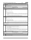
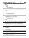
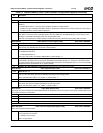
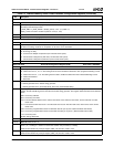
Offset 7Ch-7Fh Alpha Window 2 Control Register (R/W) Reset Value: 00000000h
31:18 Reserved.
17 LOAD_ALPHA (Load Alpha Value). (Write Only) When set to 1, this bit causes the Video Processor to load the alpha
value (in bits [7:0], ALPHA2_VAL) at the start of the next frame.
16 ALPHA2_WIN_EN (Alpha Window 2 Enable). Enable bit for Alpha Window 2.
0: Disable Alpha Window 2.
1: Enable Alpha Window 2.
Note: Valid only if video window is enabled (F4BAR0+Memory Offset 00h[0] = 1).
15:8 ALPHA2_INCR (Alpha Window 2 Increment). Specifies the alpha value increment/decrement.
This is a signed 8-bit value that is added to the alpha value for each frame. The MSB (bit 15) indicates the sign (i.e., incre-
ment or decrement). When this value reaches either the maximum or the minimum alpha value (255 or 0) it keeps that value
(i.e., it is not incremented/decremented) until it is reloaded via bit 17 (LOAD_ALPHA).
7:0 ALPHA2_VAL (Alpha Window 1 Value). Specifies the alpha value to be used for this window.
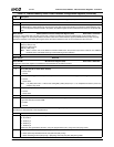
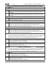
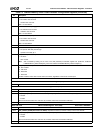
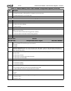
Offset 80h-83h Alpha Window 3 X Position Register (R/W) Reset Value: 00000000h
Note: H_TOTAL and H_SYNC_END are values programmed in the GX1 module’s Display Controller Timing registers
(GX_BASE+Memory Offset 8330h[26:19] and 8338h[10:3], respectively). The value of (H_TOTAL – H_SYNC_END) is some-
times referred to as “horizontal back porch”. For more information, see the AMD Geode™ GX1 Processor Data Book.
Note: Desired screen position should not be outside a video window (F4BAR0+Memory Offset 08h and 0Ch).
31:27 Reserved.
26:16 ALPHA3_X_END (Alpha Window 3 Horizontal End). Determines the horizontal end position of Alpha Window 3 (not inclu-
sive). This value is calculated according to the following formula:
Value = Desired screen position + (H_TOTAL – H_SYNC_END) – 1.
15:11 Reserved.
10:0 ALPHA3_X_START (Alpha Window 3 Horizontal Start). Determines the horizontal start position of Alpha Window 3. This
value is calculated according to the following formula:
Value = Desired screen position + (H_TOTAL – H_SYNC_END) – 2.
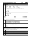
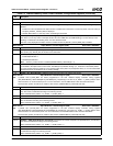
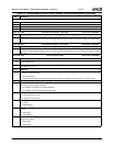
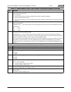
Offset 84h-87h Alpha Window 3 Y Position Register (R/W) Reset Value: 00000000h
Note: V_TOTAL and V_SYNC_END are values programmed in the GX1 module’s Display Controller Timing registers
(GX_BASE+Memory Offset 8340h[26:16] and 8348h[26:16], respectively). The value of (V_TOTAL – V_SYNC_END) is some-
times referred to as “vertical back porch”. For more information, see the AMD Geode™ GX1 Processor Data Book.
Desired screen position should not be outside a video window (F4BAR0+Memory Offset 08h and 0Ch).
31:27 Reserved.
26:16 ALPHA3_Y_END (Alpha Window 3 Vertical End). Determines the vertical end position of Alpha Window 3 (not inclusive).
This value is calculated according to the following formula:
Value = Desired screen position + (V_TOTAL – V_SYNC_END) + 2.
15:11 Reserved.
10:0 ALPHA3_Y_START (Alpha Window 3 Vertical End). Determines the vertical start position of Alpha Window 3. This value
is calculated according to the following formula:
Value = Desired screen position + (V_TOTAL – V_SYNC_END) + 1.
Table 7-9. F4BAR0+Memory Offset: Video Processor Configuration Registers (Continued)
Bit Description


