


AMD Geode™ SC1200/SC1201 Processor Data Book 17
2
Architecture Overview 32579B
2.0Architecture Overview
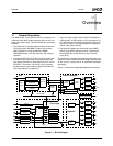
As illustrated in Figure 1-1 on page 13, the SC1200/
SC1201 processor contains the following modules in one
integrated device:
• GX1 Module:
— Combines advanced CPU performance with MMX
support, fully accelerated 2D graphics, a 64-bit
synchronous DRAM (SDRAM) interface and a PCI
bus controller. Integrates GX1 silicon revision 8.1.1.
• Video Processor Module:
— A low-power CRT and TFT support module with a
hardware video accelerator for scaling, filtering and
color space conversion, and a video input port (VIP).
Includes an NTSC/PAL TV encoder.
• Core Logic Module:
— Includes PC/AT functionality, an IDE interface, a
Universal Serial Bus (USB) interface, ACPI 1.0
compliant power management, and an audio codec
interface.
• SuperI/O Module:
— Includes two Serial Ports, an Infrared (IR) Port, a
Parallel Port, two ACCESS.bus interfaces, and a
Real-Time Clock (RTC).
2.1 GX1 Module
The GX1 processor (silicon revision 8.1.1) is the central
module of the SC1200/SC1201 processor. For detailed
information regarding the GX1 module, refer to the AMD
Geode™ GX1 Processor Data Book and the AMD
Geode™ GX1 Processor Silicon Revision 8.1.1 Specifica-
tion Update documents.
The SC1200/SC1201 processor’s device ID is contained in
the GX1 module. Software can detect the revision by read-
ing the DIR0 and DIR1 Configuration registers (see Config-
uration registers in the AMD Geode™ GX1 Processor Data
Book). The AMD Geode™ SC1200/SC1201 Processor
Specification Update document contains the specific val-
ues.
2.1.1 Memory Controller
The GX1 module is connected to external SDRAM devices.
For more information see Section 3.4.2 "Memory Interface
Signals" on page 50, and the “Memory Controller” chapter
in the AMD Geode™ GX1 Processor Data Book.
There are some differences in the SC1200/SC1201 pro-
cessor’s memory controller and the stand-alone GX1 pro-
cessor’s memory controller:
1) There is drive strength/slew control in the SC1200/
SC1201 that is not in the GX1. The bits that control
this function are in the MC_MEM_CNTRL1 and
MC_MEM_CNTRL2 registers. In the GX1 processor,
these bits are marked as reserved.
2) The SC1200/SC1201 supports two banks of memory.
The GX1 supports four banks of memory. In addition,
the SC1200/SC1201 supports a maximum of eight
devices and the GX1 supports up to 32 devices. With
this difference, the MC_BANK_CFG register is differ-
ent.
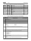
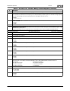
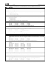
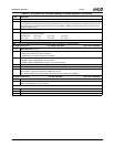
Table 2-1 on page 18 summarizes the 32-bit registers con-
tained in the SC1200/SC1201 processor’s memory control-
ler. Table 2-2 on page 18 gives detailed register/bit formats.