


52 AMD Geode™ SC1200/SC1201 Processor Data Book
Signal Definitions
32579B
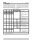
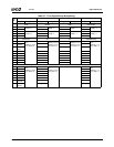
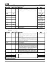
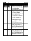
VOPD7 D20 O Video Output Port Data. The data is output from the
Video Processor in VESA Video Interface Port Rev 1.1
Task B format.
PD2+TFTD8+
F_AD2
VOPD6 A21 PD1+TFTD7+
F_AD1
VOPD5 C21 PD0+TFTD6+
F_AD0
VOPD4 B21 INIT#+TFTD5+
SMI_O
VOPD3 D21 ERR#+TFTD4+
F_CBE0#
VOPD2 B17 BUSY/WAIT#+
TFTD3+F_C/BE1#
VOPD1 D22 AFD#/DSTRB#+
TFTD2+INTR_O
VOPD0 A20 PD6+TFTD1+
F_AD6
VOPCK B18 O Video Output Port Clock. The clock output from the
Video Processor.
ACK#+TFTDE+
FPCICLK
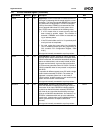
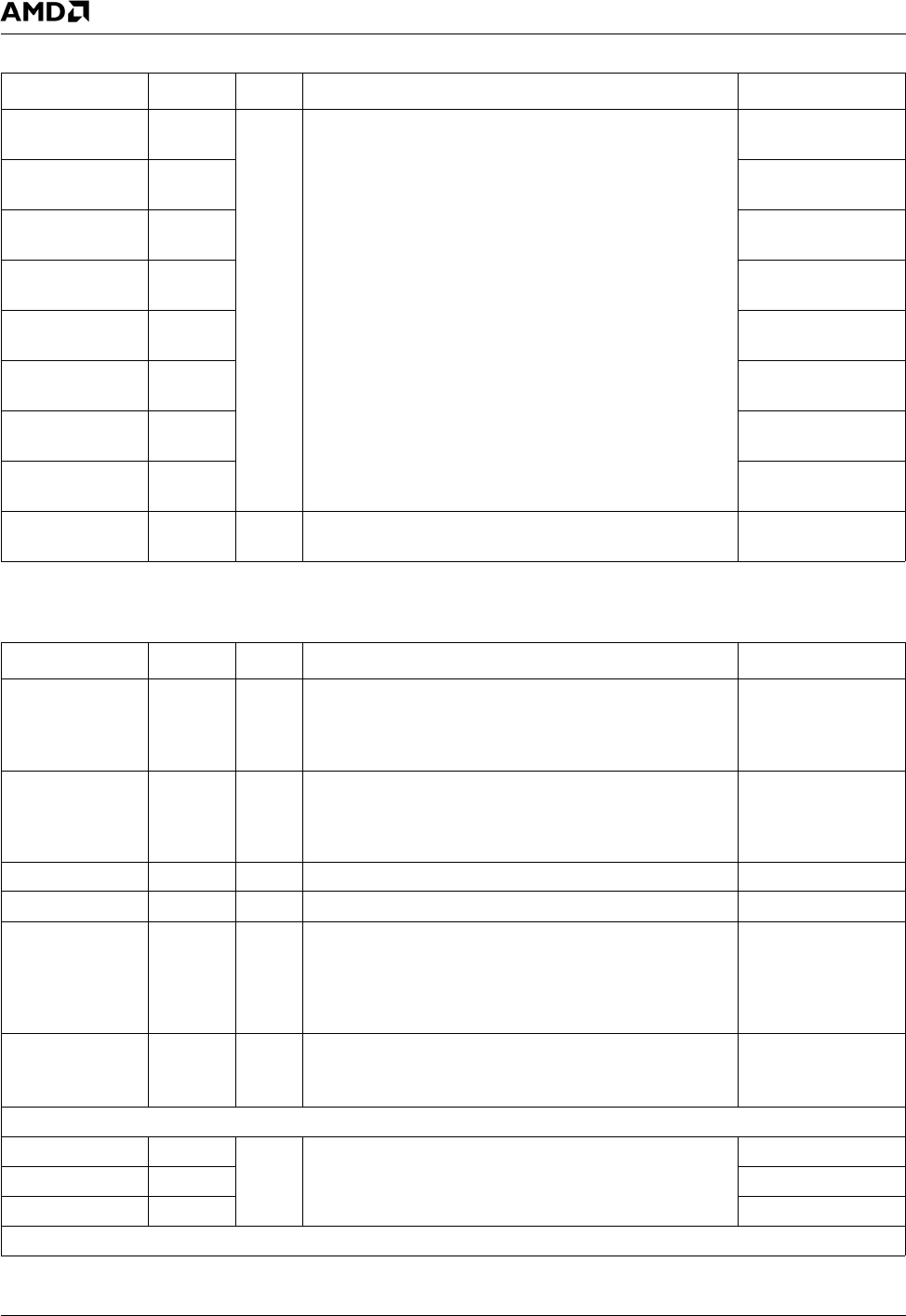
3.4.3 Video Port Interface Signals (Continued)
Signal Name Ball No. Type Description Mux
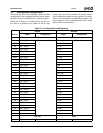
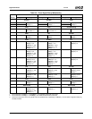
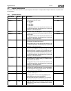
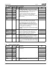
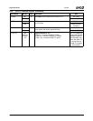
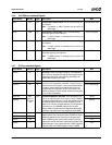
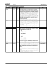
3.4.4 CRT/TFT Interface Signals
Signal Name Ball No. Type Description Mux
DDC_SCL Y1 O DDC Serial Clock. This is the serial clock for the VESA
Display Data Channel interface. It is used for monitor
communications. The DDC2B standard is supported by
this interface.
IDE_DATA10
DDC_SDA Y2 I/O DDC Serial Data. This is the bidirectional serial data sig-
nal for the VESA Display Data Channel interface. It is
used for monitor communications. The DDC2B standard
is supported by this interface.
IDE_DATA9
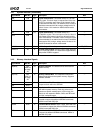
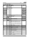
HSYNC A11 O Horizontal Sync ---
VSYNC B11 O Vertical Sync ---
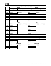
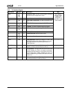
VREF D16 I/O Voltage Reference. Reference voltage for CRT PLL and
DAC. This signal reflects the internal voltage reference. If
internal voltage reference is used (recommended), leave
this ball disconnected. If an external voltage reference is
used, this input is tied to a 1.235V reference.
---
SETRES B15 I Set Resistor. This signal sets the current level for the
RED/GREEN/BLUE analog outputs. Typically, a 464 Ω,
1% resistor is connected between this ball and AV
SSCRT
.
---
On-Chip RAMDAC
RED B12 O Analog Red, Green and Blue ---
GREEN A14 ---
BLUE A15 ---
TFT (External DAC) Interface