116 AMD Geode™ SC1200/SC1201 Processor Data Book
SuperI/O Module
32579B
5.6 System Wakeup Control (SWC)
The SWC wakes up the system by sending a power-up
request to the ACPI controller in response to the following
maskable system events:
• Modem ring (RI2#)
• Audio Codec event (SDATA_IN2)
• Programmable Consumer Electronics IR (CEIR)
address
Each system event that is monitored by the SWC is fed into
a dedicated detector that decides when the event is active,
according to predetermined (either fixed or programmable)
criteria. A set of dedicated registers is used to determine
the wakeup criteria, including the CEIR address.
A Wakeup Events Status Register (WKSR) and a Wakeup
Events Control Register (WKCR) hold a Status bit and
Enable bit, respectively, for each possible wakeup event.
Upon detection of an active event, the corresponding Sta-
tus bit is set to 1. If the event is enabled (the corresponding
Enable bit is set to 1), a power-up request is issued to the
ACPI controller. In addition, detection of an active wakeup
event may be also routed to an arbitrary IRQ.
Disabling an event prevents it from issuing power-up
requests, but does not affect the Status bits. A power-up
reset is issued to the ACPI controller when both the Status
and Enable bits are set to 1 for at least one event type.
SWC logic is powered by V
SB
. The SWC control and con-
figuration registers are battery backed, powered by V
PP
.
The setup of the wakeup events, including programmable
sequences, is retained throughout power failures (no V
SB
)
as long as the battery is connected. V
PP
is taken from V
SB
if V
SB
> 2.0; otherwise, V
BAT
is used as the V
PP
source.
Hardware reset does not affect the SWC registers. They
are reset only by a SIO software reset or power-up of V
PP
.
5.6.1 Event Detection
5.6.1.1 Audio Codec Event
A low-to-high transition on SDATA_IN2 indicates the
detection of an Audio Codec event and can be used as a
wakeup event.
5.6.1.2 CEIR Address
A CEIR transmission received on IRRX1 in a pre-selected
standard (NEC, RCA or RC-5) is matched against a pro-
grammable CEIR address. Detection of matching can be
used as a wakeup event. The CEIR address detection
operates independently of the serial port with the IR (which
is powered down with the rest of the system).
Whenever an IR signal is detected, the receiver immedi-
ately enters the Active state. When this happens, the
receiver keeps sampling the IR input signal and generates
a bit string where a logic 1 indicates an idle condition and a
logic 0 indicates the presence of IR energy. The received
bit string is de-serialized and assembled into 8-bit charac-
ters.
The expected CEIR protocol of the received signal should
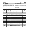
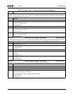
be configured through bits [5:4] of the CEIR Wakeup Con-
trol register (IRWCR) (see Table 5-30 on page 119).
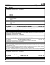
The CEIR Wakeup Address register (IRWAD) holds the
unique address to be compared with the address contained
in the incoming CEIR message. If CEIR is enabled
(IRWCR[0] = 1) and an address match occurs, then the
CEIR Event Status bit of WKSR is set to 1.
The CEIR Address Shift register (ADSR) holds the
received address which is compared with the address con-
tained in the IRWAD. The comparison is affected also by
the CEIR Wakeup Address Mask register (IRWAM) in
which each bit determines whether to ignore the corre-
sponding bit in the IRWAD.
If CEIR routing to interrupt request is enabled, the
assigned SWC interrupt request can be used to indicate
that a complete address has been received. To get this
interrupt when the address is completely received, IRWAM
should be written with FFh. Once the interrupt is received,
the value of the address can be read from ADSR.
Another parameter that is used to determine whether a
CEIR signal is to be considered valid is the bit cell time
width. There are four time ranges for the different protocols
and carrier frequencies. Four pairs of registers (IRWTRxL
and IRWTRxH) define the low and high limits of each time
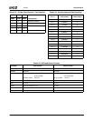
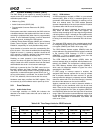
range. Table 5-26 lists the recommended time ranges limits
for the different protocols and their applicable ranges. The
values are represented in hexadecimal code where the
units are of 0.1 ms.
Table 5-26. Time Range Limits for CEIR Protocols
Time
Range
RC-5 NEC RCA
Low Limit High Limit Low Limit High Limit Low Limit High Limit
0 10h 14h 09h 0Dh 0Ch 12h
1 07h 0Bh 14h 19h 16h 1Ch
2 - - 50h 64h B4h DCh
3 - - 28h 32h 23h 2Dh


