AMD Geode™ SC1200/SC1201 Processor Data Book 261
Core Logic Module - IDE Controller Registers - Function 2
32579B
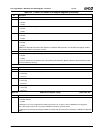
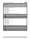
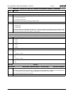
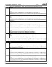
Offset 08h IDE Bus Master 1 Command Register — Secondary (R/W) Reset Value: 00h
7:4 Reserved. Must be set to 0. Must return 0 on reads.
3 Read or Write Control. Sets the direction of bus master transfers.
0: PCI reads are performed.
1: PCI writes are performed.
This bit should not be changed when the bus master is active.
2:1 Reserved. Must be set to 0. Must return 0 on reads.
0 Bus Master Control. Controls the state of the bus master.
0: Disable master.
1: Enable master.
Bus master operations can be halted by setting this bit to 0. Once an operation has been halted, it cannot be resumed. If this
bit is set to 0 while a bus master operation is active, the command is aborted and the data transferred from the drive is dis-
carded. This bit should be reset after completion of data transfer.
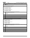
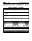
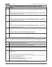
Offset 09h Not Used
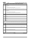
Offset 0Ah IDE Bus Master 1 Status Register — Secondary (R/W) Reset Value: 00h
7 Reserved. (Read Only)
6 Drive 1 DMA Capable. Allow Drive 1 to perform DMA transfers.
0: Disable.
1: Enable.
5 Drive 0 DMA Capable. Allow Drive 0 to perform DMA transfers.
0: Disable.
1: Enable.
4:3 Reserved. Must be set to 0. Must return 0 on reads.
2 Bus Master Interrupt. Indicates if the bus master detected an interrupt.
0: No.
1: Yes. Write 1 to clear.
1 Bus Master Error. Indicates if the bus master detected an error during data transfer.
0: No.
1: Yes. Write 1 to clear.
0 Bus Master Active. Indicates if the bus master is active.
0: No.
1: Yes.
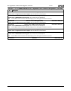
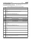
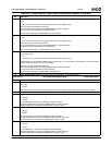
Offset 0Bh Not Used
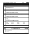
Offset 0Ch-0Fh IDE Bus Master 1 PRD Table Address — Secondary (R/W) Reset Value: 00000000h
31:2 Pointer to the Physical Region Descriptor Table. This bit field contains a PRD table pointer for IDE Bus Master 1.
When written, this field points to the first entry in a PRD table. Once IDE Bus Master 1 is enabled (Command Register bit 0
= 1), it loads the pointer and updates this field (by adding 08h) so that is points to the next PRD.
When read, this register points to the next PRD.
1:0 Reserved. Must be set to 0.
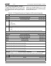
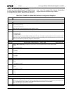
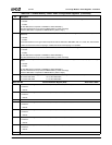
Table 6-36. F2BAR4+I/O Offset: IDE Controller Configuration Registers (Continued)
Bit Description


