


Hardware Description
3-26
© Copyright ARM Limited 1999. All rights reserved.
ARM DUI 0125A
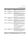
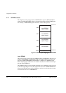
RTCK Return TCK
(to JTAG equipment)
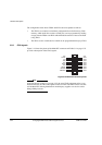
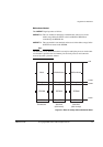
Some devices sample TCK (for example a synthesizable core
with only one clock), and this has the effect of delaying the time
at which a component actually captures data. RTCK is a
mechanism for returning the sampled clock to the JTAG
equipment, so that the clock is not advanced until the
synchronizing device captured the data. In adaptive clocking
mode, Multi-ICE is required to detect an edge on RTCK before
changing TCK. In a multiple device JTAG chain, the RTCK
output from a component connects to the TCK input of the
down-stream device. The RTCK signal on the module
connectors HDRB returns TCK to the JTAG equipment. If there
are no synchronizing components in the scan chain then it is
unnecessary to use the RTCK signal and it is connected to
ground on the motherboard.
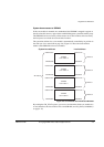
TCK Test clock
(from JTAG equipment)
TCK synchronizes all JTAG transactions. TCK connects to all
JTAG components in the scan chain. Series termination resistors
are used to reduce reflections and maintain good signal integrity.
TCK flows down the stack of modules and connects to each
JTAG component. However, if there is a device in the scan chain
that synchronizes TCK to some other clock, then all down-stream
devices are connected to the RTCK signal on that component
(see RTCK).
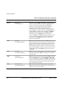
TDI Test data in
(from JTAG equipment)
TDI goes down the stack of modules to the motherboard and then
back up the stack, labelled TDO, connecting to each component
in the scan chain.
TDO Test data out
(to JTAG equipment)
TDO is the return path of the data input signal TDI. The module
connectors HDRB have two pins labelled TDI and TDO. TDI
refers to data flowing down the stack and TDO to data flowing up
the stack. The JTAG components are connected in the return path
so that the length of track driven by the last component in the
chain is kept as short as possible.
TMS Test mode select
(from JTAG equipment)
TMS controls transitions in the tap controller state machine.
TMS connects to all JTAG components in the scan chain as the
signal flows down the module stack.
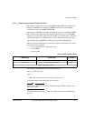
Table 3-4 JTAG signal description (continued)
Name Description Function