Level One Memory System
ARM DDI 0363E Copyright © 2009 ARM Limited. All rights reserved. 8-27
ID013010 Non-Confidential, Unrestricted Access
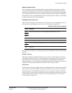
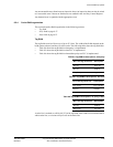
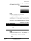
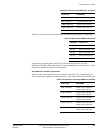
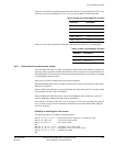
Table 8-7 shows the tag RAM cache sizes and associated RAM organization, assuming no parity
or ECC. For parity, the width of the tag RAMs must be increased by one bit. For ECC, the width
of the tag RAMs must be increased by seven bits.
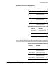
Dirty RAM
For the data cache only, the dirty RAM stores the following information:
• two bits for line outer attributes for evictions
• one line dirty bit
• four ECC code bits if the ECC build option is enabled.
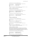
The dirty RAM array consists of one bank of up to 512 12-bit lines, 4 ways x 3 bits. If ECC is
enabled, the dirty RAM is 28 bits wide. Each line of dirty RAM contains all the information of
the four ways for a given index.
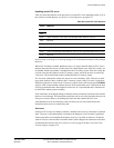
Each time a dirty bit is written, the outer bits of the line and, if implemented, the ECC code bits,
are also written. The dirty RAM is bit-enabled. Table 8-8 shows the organization of a dirty RAM
line.
Data RAM
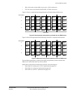
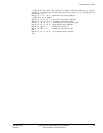
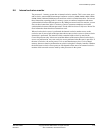
Data RAM is organized as eight banks of 32-bit wide lines, or in the instruction cache as four
banks of 64-bit wide lines. This RAM organization means that it is possible to:
• Perform a cache look-up with one RAM access, all banks selected together. This is done
for nonsequential read operations. Figure 8-3 on page 8-28 shows this.
• Select the appropriate bank RAM for sequential read operations. Figure 8-4 on page 8-28
shows this.
Table 8-7 Cache sizes and tag RAM organization
Cache size Tag RAM organization
4KB 4 banks 23 bits 32 lines
8KB 4 banks 22 bits 64 lines
16KB 4 banks 21 bits 128 lines
32KB 4 banks 20 bits 256 lines
64KB 4 banks 19 bits 512 lines
Table 8-8 Organization of a dirty RAM line
Bit in the dirty cache line Description
Bits [6:3] ECC bits, if implemented
Bits [2:1] Outer attributes that are re-encoded on AWCACHE when an eviction is sent to the AXI
bus:
01 = WB, WA
10 = WT
11 = WB, no WA
00 = Non-cacheable.
Bit [0] Dirty bit


