Debug
ARM DDI 0363E Copyright © 2009 ARM Limited. All rights reserved. 11-58
ID013010 Non-Confidential, Unrestricted Access
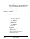
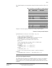
For a simple breakpoint, you can program the settings for the other control bits as Table 11-43
shows:
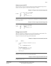
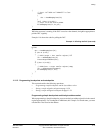
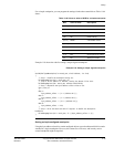
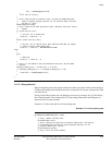
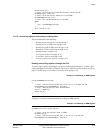
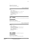
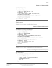
Example 11-7 shows the sequence of instructions for setting a simple breakpoint.
Example 11-7 Setting a simple breakpoint
SetSimpleBreakpoint(int break_num, uint32 address, iset_t isa)
{
// Step 1. Disable the breakpoint being set.
WriteDebugRegister(80 + break_num, 0x0);
// Step 2. Write address to the BVR, leaving the bottom 2 bits zero.
WriteDebugRegister(64 + break_num, address & 0xFFFFFFC);
// Step 3. Determine the byte address select value to use.
case (isa) of
{
// Note: The processor does not support Jazelle or ThumbEE states,
// but the ARMv7 Debug architecture does
when JAZELLE:
byte_address_select := (1 << (address & 3));
when THUMB:
byte_address_select := (3 << (address & 2));
when ARM:
byte_address_select := 15;
}
// Step 4. Write the mask and control register to enable the breakpoint.
breakpoint
WriteDebugRegister(80 + break_num, 7 | (byte_address_select << 5));
}
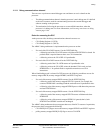
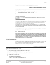
Setting a simple aligned watchpoint
The simplest and most common type of watchpoint watches for a write to a given address in
memory. In practice, a data object spans a range of addresses but is aligned to a boundary
corresponding to its size, so you must set the byte address select bits in the same way as for a
breakpoint.
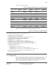
Table 11-43 Values to write to BCR for a simple breakpoint
Bits Value to write Description
[31:29]
0b000
Reserved
[28:24]
0b00000
Breakpoint address mask
[23]
0b0
Reserved
[22:20]
0b000
Meaning of BVR
[19:16]
0b0000
Linked BRP number
[15:9]
0b00
Reserved
[8:5] Derived from address Byte address select
[4:3]
0b00
Reserved
[2:1]
0b11
Supervisor access control
[0]
0b1
Breakpoint enable


