


Chapter 4 Operational Concepts and Configuration Examples
68 Avaya X330WAN User’s Guide
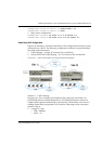
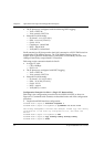
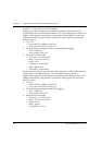
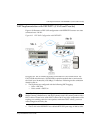
Scenario 2 - Priority DLCI and Traffic Shaping
In Figure 4.11, Site A contains four IP phones and a data LAN connected via a
P333T-PWR switch to a G700 Media Gateway. The G700 Media Gateway houses an
X330W-2USP expansion module that is connected to a Frame Relay network via a
192Kbps Frame Relay encapsulated V.35 interface. Following are the connection
details for Site A:
•Two VCs:
— One with CIR = 128Kbps, DLCI = 16
— The second with CIR = 0, DLCI = 17
• The IP phones are configured with the following DSCP tagging:
— Voice = DSCP 46
— Voice control = DSCP 34
• Network IPs (all 24 mask):
— IP phones - 1.1.1.0 (VLAN 1)
— Data - 11.11.11.0 (VLAN 2)
— Serial - 2.2.2.1
— Gatekeeper - 149.49.54.81
— MGP - 149.49.54.82
— VoIP (MGP) - 149.49.54.83
Site B contains four IP phones and a data LAN connected to a P333T-PWR switch in
a stack with a G700 Media Gateway. The G700 Media Gateway houses an
X330W-2USP expansion module that is connected to a Frame Relay network via a
192Kbps Frame Relay encapsulated V.35 interface. Following are the connection
details for Site B:
•Two VCs:
— One with CIR = 128Kbps, DLCI = 16
— The second with CIR = 0, DLCI = 17
• The IP phones are configured with DSCP tagging:
— Voice = DSCP 46
— Voice control = DSCP 34
• Network IPs (all 24 mask):
— IP phones - 3.3.3.0 (VLAN 1)
— Data - 33.33.33.0 (VLAN 2)
— Serial - 2.2.2.2
— MGP - 4.4.4.10
— VoIP (MGP) - 4.4.4.11