


5-8
Cisco 10008 Router Hardware Installation Guide
OL-0659-13
Chapter 5 Maintaining the Cisco 10008 Router
Removing and Replacing Field-Replaceable Units
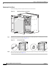
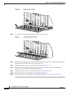
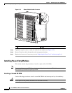
Figure 5-6 Removing the Air Filter
Step 5
Pull out the filter tray far enough to remove the air filter (Figure 5-6).
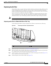
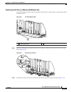
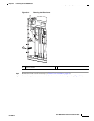
Figure 5-7 Inserting the New Air Filter
Step 6
Place the new air filter in the tray so that you can see the directional arrows located on the metal frame
(pointing up) and slide the tray into the chassis (Figure 5-7).
Step 7 Tighten the captive screws to secure the filter to the chassis (Figure 5-7).
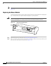
Step 8 Slide the blower module back into the chassis making sure it securely connects to the backplane
(Figure 5-12). The FANS OK LED should light (green).
Step 9 Tighten the captive screws on each side of the blower module (Figure 5-12).
Step 10 Return all interface cables through the cable management brackets.
Step 11 Replace the front cover if necessary (see the “Replacing the Front Cover” section on page 5-6).
P
R
O
C
E
S
S
O
R
O
N
LY
POW
ER
FAULT
MISW
IRE
GIGABIT ETHERNET
CH OC-12-DSO SM-IR
6XCT3–DS0
5
6XCT3–DS0
5
FAIL
PERFORMANCE ROUTING ENGINE
STATUS
ACO
CRITICAL
MINOR
MAJOR
FAIL
PERFORMANCE ROUTING ENGINE
STATUS
ACO
CRITICAL
MINOR
MAJOR
6XCT3–DS0
5
6XCT3–DS0
5
6XCT3–DS0
5
OC–12/STM–4 POS SM–IR
32220
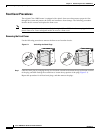
P
R
O
C
E
S
S
O
R
O
N
LY
POW
ER
FAULT
M
ISW
IRE
GIGABIT ETHERNET
CH OC-12-DSO SM-IR
6XCT3–DS0
5
6XCT3–DS0
5
FAIL
PERFORMANCE ROUTING ENGINE
STAT U S
ACO
CRITICAL
MINOR
MAJOR
FAIL
PERFORMANCE ROUTING ENGINE
STAT U S
ACO
CRITICAL
MINOR
MAJOR
6XCT3–DS0
5
6XCT3–DS0
5
6XCT3–DS0
5
OC–12/STM–4 POS SM–IR
32221