


3-26
Cisco 10008 Router Hardware Installation Guide
OL-0659-13
Chapter 3 Installing the Cisco 10008 Router
Connecting Alarm Indicators
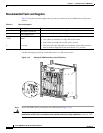
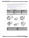
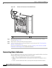
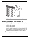
Figure 3-25 AC Power Cord Connectors in Strain Relief Devices
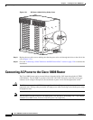
Step 3
Set the AC power cord connectors in a cord strain relief device to prevent them from accidently
disconnecting (Figure 3-25).
Step 4 Plug the power cord into the facility VAC input receptacle.
Step 5 If you are connecting audio or visual alarm indicators to your system, go to the “Connecting Alarm
Indicators” section on page 3-26.
If you are not connecting any alarm indicators, go to the “Connecting a Video Terminal to the PRE
Console Port” section on page 3-30 to continue the installation.
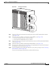
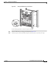
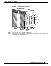
Connecting Alarm Indicators
The Cisco 10008 router provides relay contacts for optional (customer-supplied) audible or visual alarm
indicators. Relay contacts are provided for three levels of severity:
• Minor—This is an informational alarm and does not affect the system operation.
• Major—An alarm condition that affects system operation and should be investigated as soon as
possible.
• Critical—An alarm condition that affects system operation and requires immediate attention.
1 Power cord strain relief device
32235
1
3
2
4
0
A
P
R
O
C
E
S
S
O
R
O
N
L
Y
0
B
5
6
7
8
P
R
O
C
E
S
S
O
R
O
N
L
Y
P
O
W
E
R
F
A
U
L
T
P
O
W
E
R
F
A
U
L
T
C
I
S
C
O
1
0
0
0
0
L
I
N
K
T
X
R
X
F
A
I
L
GIGABIT ETHERNET
C
I
S
C
O
1
0
0
0
0
C
A
R
R
I
E
R
A
L
A
R
M
L
O
O
P
F
A
I
L
CH OC-12-DSO SM-IR
CISCO
10000
C
A
R
R
I
E
R
A
L
A
R
M
L
O
O
P
F
A
IL
6XCT3–DS0
0
5
4
3
2
1
CISCO
10000
C
A
R
R
I
E
R
A
L
A
R
M
L
O
O
P
F
A
IL
6XCT3–DS0
0
5
4
3
2
1
F
A
IL
PERFORMANCE ROUTING ENGINE
C
O
N
S
O
L
E
S
T
A
T
U
S
A
C
O
C
R
IT
IC
A
L
M
IN
O
R
M
A
J
O
R
E
T
H
E
R
N
E
T
L
I
N
K
A
C
T
I
V
I
T
Y
A
U
X
S
L
O
T
0
S
L
O
T
1
F
A
IL
PERFORMANCE ROUTING ENGINE
C
O
N
S
O
L
E
S
T
A
T
U
S
A
C
O
C
R
I
T
IC
A
L
M
IN
O
R
M
A
J
O
R
E
T
H
E
R
N
E
T
L
I
N
K
A
C
T
I
V
I
T
Y
A
U
X
S
L
O
T
0
S
L
O
T
1
CISCO
10000
C
A
R
R
I
E
R
A
L
A
R
M
L
O
O
P
F
A
IL
6XCT3–DS0
0
5
4
3
2
1
CISCO
10000
C
A
R
R
I
E
R
A
L
A
R
M
L
O
O
P
F
A
IL
6XCT3–DS0
0
5
4
3
2
1
CISCO
10000
C
A
R
R
I
E
R
A
L
A
R
M
L
O
O
P
F
A
IL
6XCT3–DS0
0
5
4
3
2
1
CISCO
10000
C
A
R
R
I
E
R
T
X
R
X
F
A
IL
OC–12/STM–4 POS SM–IR
CISCO
10000
CISCO
10000
F
A
N
S
O
K
F
A
N
F
A
I
L
U
R
E
M
U
L
T
I
-
F
A
N
F
A
I
L
U
R
E
W
hen ho
t sw
ap
pin
g th
is fan tray
,
rem
o
val a
nd rep
lacem
ent m
ust
be
done
in und
er two m
inutes or
sy
stem
sh
utdown will o
ccu
r.
CA
UTIO
N
1