


3-6
Cisco 10008 Router Hardware Installation Guide
OL-0659-13
Chapter 3 Installing the Cisco 10008 Router
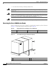
Rack-Mounting the Chassis
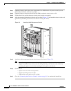
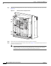
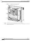
Step 1 Attach the two mounting brackets to the chassis so the flanges are positioned at the center of the chassis
(Figure 3-3).
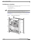
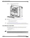
Figure 3-4 Attaching Chassis to Equipment Rack
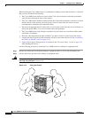
Step 2
Lift the chassis into position between the rack posts (requires two people).
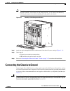
Step 3 Align the mounting bracket holes with the rack post holes (Figure 3-4) and attach the chassis to the rack
(performed by the third person).
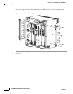
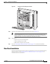
Note The cable management bracket consists of two pieces (the cable guide and channel), and is
shipped assembled. If you want to use the cable guide only, you can remove the channel by
loosening the captive screws before attaching the cable guide to the chassis.
30013
1
3
2
4
0A
PROCESSOR ONLY
0B
5
6
7
8
PROCESSOR ONLY
P
O
W
E
R
F
A
U
L
T
M
I
S
W
I
R
E
P
O
W
E
R
F
A
U
L
T
M
I
S
W
IR
E
C
IS
C
O
1
0
0
0
0
LIN
K
TX
R
X
F
A
IL
GIGABIT ETHERNET
CISCO
10000
C
A
R
R
I
E
R
A
L
A
R
M
L
O
O
P
F
A
I
L
CH OC-12-DSO SM-IR
C
IS
C
O
10
00
0
CARRIER
ALARM
LOOP
F
A
I
L
6XCT3–DS0
0
5
4
3
2
1
C
IS
C
O
1
000
0
CARRIER
ALARM
LOOP
F
A
IL
6XCT3–DS0
0
5
4
3
2
1
F
A
I
L
PERFORMANCE ROUTING ENGINE
C
ON
SO
LE
S
T
A
T
U
S
A
C
O
C
R
I
T
I
C
A
L
M
I
N
O
R
M
A
J
O
R
E
TH
ER
NE
T
LIN
K
A
CTIVITY
A
U
X
S
L
O
T
0
S
L
O
T
1
F
A
I
L
PERFORMANCE ROUTING ENGINE
CO
NSO
LE
S
T
A
T
U
S
A
C
O
C
R
I
T
I
C
A
L
M
I
N
O
R
M
A
J
O
R
ETH
ER
NE
T
LIN
K
ACTIVITY
AUX
S
L
O
T
0
S
L
O
T
1
C
IS
C
O
10
000
CARRIER
ALARM
LOOP
F
A
IL
6XCT3–DS0
0
5
4
3
2
1
C
ISC
O
1
000
0
CARRIER
ALARM
LOOP
F
A
IL
6XCT3–DS0
0
5
4
3
2
1
C
IS
C
O
1
000
0
CARRIER
ALARM
LOOP
F
A
IL
6XCT3–DS0
0
5
4
3
2
1
C
IS
C
O
100
0
0
CARRIER
TX
RX
F
A
IL
OC–12/STM–4 POS SM–IR
F
A
N
S
O
K
F
A
N
F
A
I
L
U
R
E
M
U
L
T
I
-
F
A
N
F
A
I
L
U
R
E
When hot swapping this fan tray,
removal and replacement must
be done in under two minutes or
system shutdown will occur.
CAUTION
C
ISC
O
1
000
0
C
IS
C
O
1
000
0