


5-36
Cisco 10008 Router Hardware Installation Guide
OL-0659-13
Chapter 5 Maintaining the Cisco 10008 Router
Connecting Alarm Indicators
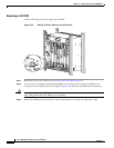
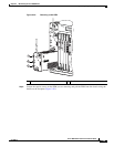
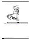
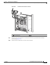
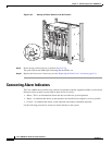
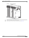
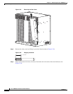
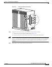
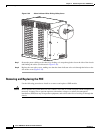
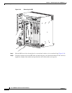
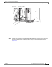
Figure 5-38 Alarm Indicator Wires Exiting Safety Cover
Step 7
Secure the power cabling to the chassis by feeding a tie wrap through the slot on the side of the chassis
and binding the cables (see blowout in Figure 5-38).
Step 8 Replace the rear safety cover, making sure that the alarm indicator wires exit through the holes on the
side of the cover (Figure 5-38).
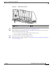
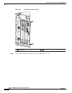
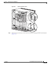
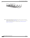
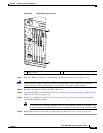
Removing and Replacing the PRE
Use the following procedure to install or to remove and replace a PRE module.
Caution Do not operate the system unless all slots contain a line card or a blank faceplate. Blank faceplates are
necessary in empty slots to prevent exposure to hazardous voltages, to reduce electromagnetic
interference (EMI) that may disrupt other equipment, and to direct the flow of cooling air through the
chassis.
32693