


3-13
Cisco 10008 Router Hardware Installation Guide
OL-0659-13
Chapter 3 Installing the Cisco 10008 Router
Connecting the Chassis to Ground
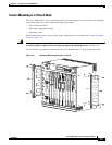
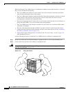
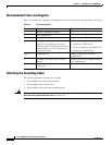
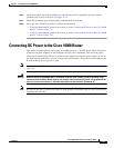
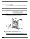
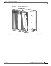
Note The cable management bracket consists of two pieces (the cable guide and channel), and is
shipped assembled. If you want to use the cable guide only, you can remove the channel by
loosening the captive screws before attaching the cable guide to the chassis.
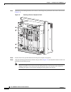
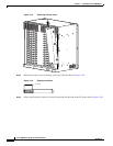
Figure 3-11 Attaching Cable Management Bracket
Step 3
Attach the cable management bracket to the bottom of the chassis if you are using it (Figure 3-11).
Step 4 Check that all
–
Ejector levers are in the closed position.
–
PRE and line card captive screws are tight.
Step 5 Go to the “Connecting the Chassis to Ground” section on page 3-13 to continue the installation.
Connecting the Chassis to Ground
Connecting the Cisco 10008 chassis to earth ground is required for all DC powered installations, and any
AC powered installation where compliance with Telcordia (formerly Bellcore) grounding requirements
is necessary. Have the recommended tools and supplies available before you begin this procedure (see
Table 3-1).
Warning
Never defeat the ground conductor or operate the equipment in the absence of a suitably installed
ground conductor. Contact the appropriate electrical inspection authority or an electrician if you are
uncertain that suitable grounding is available.
Statement 93
76215
1
3
2
4
0A
PROCESSOR ONLY
0B
5
6
7
8
PROCESSOR ONLY
P
O
W
E
R
F
A
U
L
T
M
I
S
W
IR
E
P
O
W
E
R
F
A
U
L
T
M
I
S
W
I
R
E
C
IS
C
O
1
0
0
0
0
L
I
N
K
T
X
R
X
F
A
I
L
GIGABIT ETHERNET
CISCO
10000
C
A
R
R
I
E
R
A
L
A
R
M
L
O
O
P
F
A
I
L
CH OC-12-DSO SM-IR
C
IS
C
O
1
0
0
0
0
CARRIER
ALARM
LOOP
F
A
IL
6XCT3–DS0
0
5
4
3
2
1
C
IS
C
O
1
0
0
0
0
CARRIER
ALARM
LOOP
F
A
IL
6XCT3–DS0
0
5
4
3
2
1
F
A
IL
PERFORMANCE ROUTING ENGINE
C
O
N
S
O
L
E
S
T
A
T
U
S
A
C
O
C
R
IT
I
C
A
L
M
IN
O
R
M
A
J
O
R
E
T
H
E
R
N
E
T
L
I
N
K
A
C
T
I
V
I
T
Y
A
U
X
S
L
O
T
0
S
L
O
T
1
F
A
I
L
PERFORMANCE ROUTING ENGINE
C
O
N
S
O
L
E
S
T
A
T
U
S
A
C
O
C
R
I
T
I
C
A
L
M
I
N
O
R
M
A
J
O
R
E
T
H
E
R
N
E
T
L
I
N
K
A
C
T
I
V
I
T
Y
A
U
X
S
L
O
T
0
S
L
O
T
1
C
I
S
C
O
1
0
0
0
0
CARRIER
ALARM
LOOP
F
A
IL
6XCT3–DS0
0
5
4
3
2
1
C
I
S
C
O
1
0
0
0
0
CAR
RIER
ALARM
LOOP
F
A
IL
6XCT3–DS0
0
5
4
3
2
1
C
IS
C
O
1
0
0
0
0
CARRIER
ALARM
LOOP
F
A
I
L
6XCT3–DS0
0
5
4
3
2
1
C
IS
C
O
1
0
0
0
0
CARRIER
TX
RX
F
A
I
L
OC–12/STM–4 POS SM–IR
C
IS
C
O
1
0
0
0
0
C
I
S
C
O
1
0
0
0
0
F
A
N
S
O
K
F
A
N
F
A
I
L
U
R
E
M
U
L
T
I
-
F
A
N
F
A
I
L
U
R
E
When hot swapping this fan tray,
removal and replacement must
be done in under two minutes or
system shutdown will occur.
CAUTION