


4-2
Cisco 10008 Router Hardware Installation Guide
OL-0659-13
Chapter 4 Starting and Configuring the Router
Configuring the Cisco 10008 Router at Startup
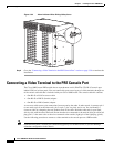
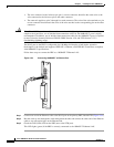
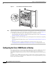
Figure 4-1 Cisco 10008 Router DC PEM Power Switches
Step 1 Remove the tape from the building circuit breaker switches and set the circuit breaker to the On position.
At the front of the chassis, set the circuit breakers on the PEM units to the on ( | ) position (Figure 4-1).
a. The PEM Power LED lights (green), indicating that power is available to the chassis.
If any Fault LEDs (such as Miswire or Single Fan Failure) light (yellow), see the “Troubleshooting
Installation Problems” section on page 4-12.
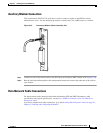
b. The blower module Fan OK LED lights (green), indicating that all fans in the blower are operating
properly.
If any Fan Failure LEDs light (yellow), see the “Troubleshooting Installation Problems” section on
page 4-12.
c. When the system boot is complete, the PRE begins to initialize the line cards. Go to the
“Configuring the Cisco 10008 Router at Startup” section on page 4-2 to configure the line cards.
Configuring the Cisco 10008 Router at Startup
This section explains how to create a basic running configuration for your Cisco 10008 router using the
Cisco 10008 setup facility or the Cisco IOS command line interface (CLI). For information on
modifying the configuration after you create it, see the Cisco IOS configuration and command reference
guides.
To configure a Cisco 10008 router from the console, you must connect a terminal or terminal server to
the router's console port. To configure the Cisco 10008 router over your management Ethernet, you must
have the router’s IP address available.
30037
1
3
2
4
0A
PROCESSOR ONLY
0B
5
6
7
8
PROCESSOR ONLY
P
O
W
E
R
F
A
U
L
T
M
I
S
W
IR
E
POWER
FAULT
MISWIRE
P
O
W
E
R
F
A
U
L
T
M
I
S
W
I
R
E
C
I
S
C
O
1
0
0
0
0
L
IN
K
T
X
R
X
F
A
IL
GIGABIT ETHERNET
C
I
S
C
O
1
0
0
0
0
C
A
R
R
IE
R
A
LA
R
M
L
O
O
P
F
A
IL
CH OC-12-DSO SM-IR
C
ISCO
10
000
C
A
R
R
I
E
R
A
L
A
R
M
L
O
O
P
F
A
I
L
6XCT3–DS0
0
5
4
3
2
1
CIS
CO
10000
C
A
R
R
I
E
R
A
L
A
R
M
L
O
O
P
F
A
I
L
6XCT3–DS0
0
5
4
3
2
1
F
A
IL
PERFORMANCE ROUTING ENGINE
C
O
N
S
O
L
E
S
T
A
T
U
S
A
C
O
C
R
I
T
I
C
A
L
M
IN
O
R
M
A
J
O
R
E
T
H
E
R
N
E
T
L
I
N
K
A
C
T
I
V
I
T
Y
A
U
X
S
L
O
T
0
S
L
O
T
1
F
A
IL
PERFORMANCE ROUTING ENGINE
C
O
N
S
O
L
E
S
T
A
T
U
S
A
C
O
C
R
I
T
I
C
A
L
M
IN
O
R
M
A
J
O
R
E
T
H
E
R
N
E
T
L
I
N
K
A
C
T
I
V
I
T
Y
A
U
X
S
L
O
T
0
S
L
O
T
1
C
ISCO
10000
C
A
R
R
I
E
R
A
L
A
R
M
L
O
O
P
F
A
I
L
6XCT3–DS0
0
5
4
3
2
1
C
ISCO
10000
C
A
R
R
I
E
R
A
L
A
R
M
L
O
O
P
F
A
I
L
6XCT3–DS0
0
5
4
3
2
1
CISCO
100
00
C
A
R
R
I
E
R
A
L
A
R
M
L
O
O
P
F
A
I
L
6XCT3–DS0
0
5
4
3
2
1
C
ISCO
10000
C
A
R
R
I
E
R
T
X
R
X
F
A
I
L
OC–12/STM–4 POS SM–IR
CISC
O
100
00
CISCO
10000
FA
N
S
O
K
F
A
N
FA
IL
U
R
E
M
U
LT
I-
F
A
N
F
AI
L
U
R
E
When hot swapping this fan tray,
rem
oval and r
eplacement must
be
done in under tw
o m
in
utes or
system shutdown will occur.
CAUTION