


3-16
Cisco 10008 Router Hardware Installation Guide
OL-0659-13
Chapter 3 Installing the Cisco 10008 Router
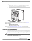
Connecting the Chassis to Ground
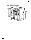
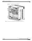
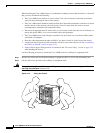
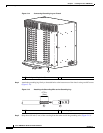
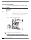
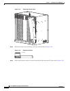
Figure 3-14 Connecting Grounding Lug to Chassis
Step 4
Attach the grounding lug firmly to threaded holes at the bottom rear of the chassis using two M5 screws
(Figure 3-14).
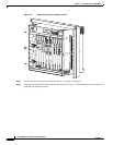
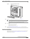
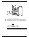
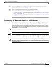
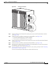
Figure 3-15 Attaching the Grounding Wire to the Grounding Lug
Step 5
Strip about 3/4 inch (2 cm) of the covering from the other end of the grounding wire (Figure 3-15).
1 Threaded grounding holes (2)
132825
1
1 Wire 2 Grounding lug
132826
1
2
0.75 in.
(2cm)