


3-18
Cisco 10008 Router Hardware Installation Guide
OL-0659-13
Chapter 3 Installing the Cisco 10008 Router
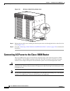
Connecting DC Power to the Cisco 10008 Router
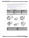
Recommended Tools and Supplies
Table 3-2 lists the tools and supplies that you need to connect the Cisco 10008 router to DC power
sources.
Use the following procedure to connect the chassis to a DC power source:
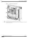
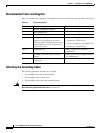
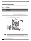
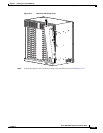
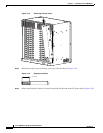
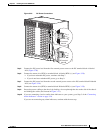
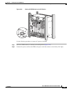
Figure 3-16 Setting DC PEM Switches to the Off Position
Step 1 Set the DC PEM switch (or switches) to the Off position (Figure 3-16).
Warning
This product requires short-circuit (overcurrent) protection, to be provided as part of the building
installation. Install only in accordance with national and local wiring regulations.
Statement 1045
Table 3-2 Tools and Supplies
Quantity Description Comments
1 Flat-blade screwdriver —
1 Wire stripping tool —
2 or 4 (length
varies)
2
10 AWG (minimum) wire
cables
Tie wraps
Cables must reach from the Cisco 10008 router to the DC power source.
• Two cables are needed for a single DC power source.
• Four cables are needed for two DC power sources.
• The end of the cable intended to be connected to the chassis needs to
have insulation stripped back not more than 0.4 in. (10 mm).
30019
1
3
2
4
0
A
P
R
O
C
E
S
S
O
R
O
N
L
Y
0
B
5
6
7
8
P
R
O
C
E
S
S
O
R
O
N
L
Y
P
O
W
E
R
F
A
U
L
T
M
I
S
W
I
R
E
P
O
W
E
R
F
A
U
L
T
M
I
S
W
I
R
E
PORT0
PORT1
PORT2
PORT3
PORT4
PORT5
FAIL
C
A
A
L
A
R
M
L
O
O
P
C10000
6CT3
PORT0
PORT1
PORT2
PORT3
PORT4
PORT5
FAIL
C
A
A
L
A
R
M
L
O
O
P
C10000
6CT3
PORT0
PORT1
PORT2
PORT3
PORT4
PORT5
FAIL
C
A
A
L
A
R
M
L
O
O
P
C10000
6CT3
PORT0
PORT1
PORT2
PORT3
PORT4
PORT5
FAIL
C
A
A
L
A
R
M
L
O
O
P
C10000
6CT3
C
IS
C
O
1
0
0
0
0
L
I
N
K
T
X
R
X
F
A
I
L
GIGABIT ETHERNET
C
IS
C
O
1
0
0
0
0
C
A
R
R
I
E
R
A
L
A
R
M
L
O
O
P
F
A
I
L
CH OC-12-DSO SM-IR
C
I
S
C
O
1
0
0
0
0
CARRIER
A
LARM
LOO
P
FAIL
6XCT3–DS0
0
5
4
3
2
1
C
I
S
C
O
1
0
0
0
0
C
ARRIER
ALARM
LOOP
FAIL
6XCT3–DS0
0
5
4
3
2
1
PERFORMANCE ROUTING ENGINE
A
L
A
R
M
S
C
I
S
C
O
1
0
0
0
0
A
C
T
I
V
IT
Y
L
I
N
K
C
R
IT
I
C
A
L
M
A
J
O
R
M
IN
O
R
A
C
O
S
L
O
T
0
S
T
A
T
U
S
F
A
IL
B
IT
S
P/N
ESR-PRE3
C
O
N
S
O
L
E
E
T
H
E
R
N
E
T
L
IN
K
A
C
T
I
V
IT
Y
A
U
X
PERFORMANCE ROUTING ENGINE
A
L
A
R
M
S
C
I
S
C
O
1
0
0
0
0
A
C
T
I
V
I
T
Y
L
I
N
K
C
R
IT
IC
A
L
M
A
J
O
R
M
IN
O
R
A
C
O
S
L
O
T
0
S
T
A
T
U
S
F
A
IL
B
IT
S
P/N
ESR-PRE3
C
O
N
S
O
L
E
E
T
H
E
R
N
E
T
L
I
N
K
A
C
T
I
V
I
T
Y
A
U
X
C
I
S
C
O
1
0
0
0
0
CARRIER
ALARM
LOOP
FAIL
6XCT3–DS0
0
5
4
3
2
1
C
I
S
C
O
1
0
0
0
0
CARRIER
ALA
RM
LOO
P
FAIL
6XCT3–DS0
0
5
4
3
2
1
C
I
S
C
O
1
0
0
0
0
CARR
IER
ALARM
LOOP
FAIL
6XCT3–DS0
0
5
4
3
2
1
C
I
S
C
O
1
0
0
0
0
CARRIER
TX
RX
FAIL
OC–12/STM–4 POS SM–IR
F
A
N
S
O
K
F
A
N
F
A
IL
U
R
E
M
U
L
T
I-
F
A
N
F
A
IL
U
R
E
When hot swapping this fan tray,
removal and replacement must
be done in under two minutes or
system shutdown will occur.
CAUTION
POWER
FAULT
MISWIRE