


3-21
Cisco 10008 Router Hardware Installation Guide
OL-0659-13
Chapter 3 Installing the Cisco 10008 Router
Connecting DC Power to the Cisco 10008 Router
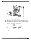
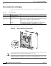
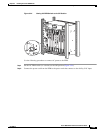
Figure 3-20 DC Power Connections
Step 5
Connect the DC power lead from the first external power source to the DC terminal block A labeled
–48V (Figure 3-20).
Step 6 Connect the return wire (RTN) to terminal block A labeled RTN (+) (see Figure 3-20).
• If you have redundant DC power, continue with Step 7.
• If you do not have redundant DC power, go to Step 9.
Step 7 Connect the DC power lead from the second external power source to the DC terminal block B labeled
–48V (see Figure 3-20).
Step 8 Connect the return wire (RTN) to terminal block B labeled RTN (+) (see Figure 3-20).
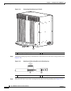
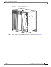
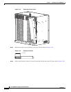
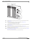
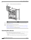
Step 9 Secure the power cabling to the chassis by feeding a tie wrap through the slot on the side of the chassis
and binding the cables (see blowout in Figure 3-21).
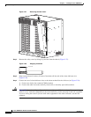
Step 10 If you are connecting visual or audio alarm indicators to your system, go to Step 3 of the “Connecting
Alarm Indicators” section on page 3-26.
If you are not connecting any alarm indicators, continue with the next step.
30024
RTN (+)
DC terminal
block B
–48/–60
V
RTN (+)
–48/–60
V
DC terminal
block A