


3-29
Cisco 10008 Router Hardware Installation Guide
OL-0659-13
Chapter 3 Installing the Cisco 10008 Router
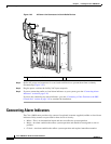
Connecting Alarm Indicators
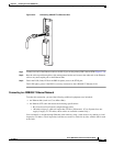
Figure 3-29 Alarm Terminal Block Connections
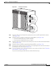
Step 5 Repeat steps 3 and 4 for any remaining alarm indicators.
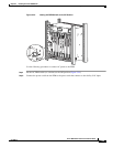
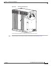
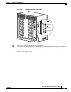
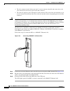
Step 6 Secure the power cabling to the chassis by feeding a tie wrap through the slot on the side of the chassis
and binding the wires (see blowout in Figure 3-30).
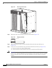
Step 7 Replace the rear safety cover, making sure that the alarm indicator wires exit through the hole on the
side of the cover (Figure 3-30).
32694
MINOR
MAJOR
CRITICAL
ALARMS
50VA
SELV max
NC
COM
NO
NC
COM
NO
NC
COM
NO